

Austempered Ductile Iron (ADI): The Hardened CGI Strategy
Austempered ductile iron (ADI) is a family of ductile (nodular) iron castings that have been heat-treated through an austempering process to produce an ausferritic microstructure — a combination of acicular ferrite and high-carbon stabilized austenite. This unique structure gives ADI tensile strengths of 130,000–230,000 PSI (895–1,585 MPa) with elongation of 1–11%, combining the strength of hardened steel with the damping capacity and castability of ductile iron.
ADI grades (per ASTM A897/A897M) range from Grade 1 (130 ksi tensile, 10% elongation, HRC 28–32) to Grade 5 (230 ksi tensile, 1% elongation, HRC 43–48). Common applications include crankshafts, camshafts, gears, suspension components, mining equipment, railroad car parts, and heavy-duty hydraulic cylinder components. ADI competes directly with forged and hardened alloy steels at 20–30% lower cost per pound and 10% lower weight due to its lower density (7.1 g/cm³ vs. 7.85 g/cm³ for steel).
The Machining Challenge: Hardness Meets Graphite Nodules
ADI machining is characterized by several unique challenges:
- Hardness: Grade 3–5 ADI ranges from HRC 33–48, requiring tooling designed for hardened materials.
- Abrasive graphite nodules: The 10–15% volume fraction of graphite nodules in the iron matrix act as micro-abrasive particles that wear cutting edges through micro-chipping and flank wear.
- Variable hardness: Casting sections cool at different rates, creating hardness variation of HRC 3–5 within a single casting. Tools must handle this variability without chipping.
- Interrupted cuts: Casting features such as cored holes, bolt holes, and parting lines create frequent interrupted cuts that test tool edge toughness.
Recommended Cutting Tool Materials
Coated Carbide (Primary Choice)
CVD-coated carbide inserts with multi-layer TiCN/Al₂O₃ coatings are the standard for ADI machining. The coating provides wear resistance against the abrasive graphite nodules while the tough carbide substrate resists chipping on interrupted cuts.
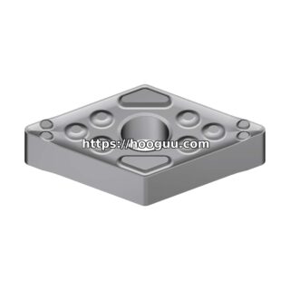
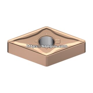
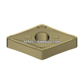
- Turning (roughing, Grade 1–3): CVD TiCN/Al₂O₃, ISO P20–P30 or M20–M30. Inserts: CNMG 120408, WNMG 080408, DNMG 150612. Edge prep: 0.004–0.008″ T-land at 20–25°. Rake angle: 0–10°.
- Turning (roughing, Grade 4–5): CVD TiCN/Al₂O₃, ISO P15–P25. Inserts: CNMG 120408, SNMG 120408. Edge prep: 0.005–0.010″ hone or T-land. Rake: −5° to +5°.
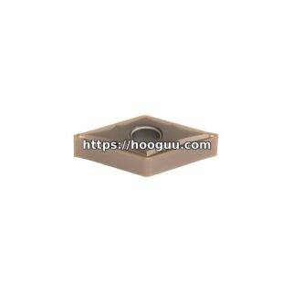
- Turning (finishing): PVD TiAlN-coated, ISO P10–P20. CCMT 09T304, VBMT 160404. Positive rake: 10–20°. Sharp edge with light hone.
- Milling: CVD-coated indexable inserts, APKT 1604PDER, SPKT 120408. Tough substrate with reinforced edge.
- Drilling: Solid carbide or indexable-insert drills, TiAlN-coated, 140° point angle.
CBN (Cubic Boron Nitride) for Hard Grades
CBN inserts (ISO BZN, 50–90% CBN content) are recommended for finish turning and hard turning of Grade 4 and Grade 5 ADI (HRC 40–48). CBN provides 5–10× the tool life of carbide at higher speeds and produces excellent surface finishes.
- Finish turning (HRC 40–48): CBN inserts, speed 600–1,000 SFM (183–305 m/min). Feed: 0.003–0.006 IPR. Depth: 0.005–0.020″. Edge hone: 0.001–0.003″. Tool life: 60–150 minutes per edge.
- Hard milling: CBN-tipped face mills and end mills for finish profiling. Speed 500–800 SFM. Light cuts only.
Ceramic (Si₃N₄ / SiAlON)
Silicon nitride (Si₃N₄) and SiAlON ceramic inserts can be used for high-speed roughing of Grade 1–3 ADI at speeds of 1,500–2,500 SFM. Ceramics offer very high metal removal rates but are limited to continuous cuts — interrupted cutting with ceramics causes rapid edge chipping.
Cutting Parameters: Turning ADI
| Operation / Grade | Speed (SFM) | Speed (m/min) | Feed (IPR) | Feed (mm/rev) | DOC (in) | DOC (mm) |
|---|---|---|---|---|---|---|
| Rough (Grade 1–2, HRC 28–33) | 350–500 | 107–152 | 0.008–0.014 | 0.20–0.35 | 0.080–0.150 | 2.0–3.8 |
| Rough (Grade 3, HRC 33–38) | 300–450 | 91–137 | 0.008–0.012 | 0.20–0.30 | 0.060–0.120 | 1.5–3.0 |
| Rough (Grade 4–5, HRC 38–48) | 200–350 | 61–107 | 0.006–0.010 | 0.15–0.25 | 0.040–0.100 | 1.0–2.5 |
| Semi-Finish (all grades) | 350–550 | 107–168 | 0.005–0.008 | 0.13–0.20 | 0.020–0.060 | 0.5–1.5 |
| Finish (Grade 1–3) | 500–700 | 152–213 | 0.003–0.005 | 0.08–0.13 | 0.005–0.020 | 0.13–0.50 |
| Finish (Grade 4–5) | 350–500 | 107–152 | 0.002–0.004 | 0.05–0.10 | 0.005–0.015 | 0.13–0.38 |
| CBN Finish (HRC 40–48) | 600–1,000 | 183–305 | 0.003–0.006 | 0.08–0.15 | 0.005–0.020 | 0.13–0.50 |
Tool life targets: carbide roughing 20–45 minutes per edge, carbide finishing 40–90 minutes, CBN finishing 60–150 minutes.
Cutting Parameters: Milling ADI
| Operation | Speed (SFM) | Feed/Tooth (IPT) | Feed/Tooth (mm) | Axial DOC | Radial DOC |
|---|---|---|---|---|---|
| Face Milling (rough, Grade 1–3) | 300–450 | 0.006–0.010 | 0.15–0.25 | 0.080–0.150 in | 60–75% of Ø |
| Face Milling (rough, Grade 4–5) | 200–350 | 0.005–0.008 | 0.13–0.20 | 0.060–0.120 in | 60–75% of Ø |
| End Milling | 250–400 | 0.004–0.007 | 0.10–0.18 | 1.0× Ø | 10–25% of Ø |
| Slot Milling | 200–300 | 0.003–0.005 | 0.08–0.13 | 0.5× Ø | Full width |
| Thread Milling | 250–400 | 0.002–0.004 IPT | 0.05–0.10 | Full thread depth | Helical interpolation |
Cutting Parameters: Drilling and Tapping
| Operation | Speed (SFM) | Feed (IPR) | Notes |
|---|---|---|---|
| Drilling (≤ 1/4″) | 80–120 | 0.002–0.003 | 140° split point, peck 2× Ø |
| Drilling (1/4″ – 1/2″) | 100–150 | 0.003–0.005 | Peck cycle 3× Ø |
| Drilling (> 1/2″) | 120–180 | 0.005–0.007 | Pilot then step drill |
| Tapping (Grade 1–3) | 15–25 SFM | — | Spiral-point, TiN-coated HSS |
| Tapping (Grade 4–5) | 8–15 SFM | — | Thread milling preferred |
Edge Preparation: Critical for ADI
The interrupted-cut nature of cast ADI components makes edge preparation one of the most important factors in tool performance:
- Roughing: T-land or chamfer of 0.004–0.010″ (0.10–0.25 mm) at 20–25° angle. This reinforces the edge against micro-chipping during entry into interrupted cuts (cored holes, casting parting lines, scale pockets).
- Semi-finishing: Light hone of 0.002–0.004″ (0.05–0.10 mm). Balances edge strength with cutting sharpness.
- Finishing: Light hone of 0.001–0.002″ (0.025–0.05 mm) or sharp edge with minimal preparation. Maximizes surface finish quality.
- CBN tools: Hone of 0.001–0.003″ (0.025–0.075 mm) with a negative land for hard turning applications.
Handling the Casting Skin
As-cast ADI surfaces often have a decarburized skin (0.010–0.040″ thick) that is softer but more abrasive than the bulk material due to sand inclusions and oxide scale from the casting and austempering processes.
- First pass must cut below the skin. Depth of cut on the first roughing pass should be 0.080–0.120″ minimum to get below the casting skin and into the uniform ausferritic matrix.
- Use tougher grades for skin passes. ISO P25–P35 or M25–M35 carbide grades with heavy edge preparation handle the abrasive skin better than harder finishing grades.
- Reduce speed on skin cuts. Drop speed by 20–30% for the first pass through the skin, then increase to standard speeds for subsequent passes in the clean matrix.
Coolant Strategy
Flood coolant is recommended for ADI machining, particularly for drilling, tapping, and interrupted turning operations where thermal shock can crack carbide edges:
- Standard flood: Semi-synthetic or synthetic coolant at 8–10% concentration, 5–8 GPM directed at the cutting zone.
- Through-tool coolant: 200–400 PSI for drilling and deep boring operations.
- High-pressure coolant: 1,000–3,000 PSI for turning operations. High-pressure coolant breaks chips effectively and extends tool life by 20–40% on continuous turning.
- Dry machining option: For rough milling of large castings, air blast with MQL is acceptable if the machine is equipped with adequate chip evacuation. The high thermal conductivity of ductile iron (35–40 W/m·K) helps dissipate heat from the cutting zone.
Surface Finish Expectations
| Process | Surface Finish (μin Ra) | Surface Finish (μm Ra) |
|---|---|---|
| Rough turned | 125–250 | 3.2–6.3 |
| Semi-finish turned | 63–125 | 1.6–3.2 |
| Finish turned (carbide) | 32–63 | 0.8–1.6 |
| CBN finish turned | 16–32 | 0.4–0.8 |
| Ground | 8–16 | 0.2–0.4 |
Comparison to Competing Materials
When evaluating ADI versus alternative materials for a machined component:
- ADI vs. hardened steel (4140/4340): ADI machines 20–30% faster at equivalent hardness, costs 20–30% less per pound, weighs 10% less, and provides superior vibration damping. Steel offers higher tensile strength at HRC 50+.
- ADI vs. standard ductile iron: ADI is 2–3× stronger but 30–50% more expensive to machine due to higher hardness and abrasiveness.
- ADI vs. CGI (compacted graphite iron): ADI has higher strength and ductility. CGI machines slightly easier due to lower hardness. Both contain graphite that abrades tools.
Summary
Austempered ductile iron requires the same tooling discipline as hardened steel, with additional attention to the abrasive effect of graphite nodules and the interrupted-cut nature of cast components. CVD-coated carbide at 200–700 SFM with robust edge preparation is the standard for roughing; CBN inserts at 600–1,000 SFM deliver premium finishing performance on Grade 4–5 material. First-pass depth must penetrate the casting skin, and tool edge preparation must withstand interrupted cuts at bolt holes and cored features. With proper parameters, ADI provides a cost-effective alternative to forged steel in high-strength structural applications.
Shop Related Products at HOOGUU