The Challenge of Machining Forged Crankshafts
Automotive crankshafts are among the highest-volume precision-machined components in the world. A typical V6 engine crankshaft is forged from microalloyed steel (such as 38MnVS6 or C70S6) and requires machining of main journals, pin journals, thrust faces, oil holes, and balance pads. With production volumes of 500,000-2,000,000 units per year at major OEMs, tool life and cycle time directly drive cost per part.
Material Properties
Forged crankshaft steels are designed for controlled cooling after forging, eliminating the need for heat treatment:
- 38MnVS6 (DIN 1.1301): Tensile strength of 850-1,000 MPa, hardness of 250-290 HB. Contains 0.38% C, 1.5% Mn, 0.07% V. The vanadium provides precipitation strengthening during air cooling.
- C70S6: Higher carbon (0.70%) for improved wear resistance. Hardness of 270-310 HB, tensile strength of 900-1,050 MPa.
- 42CrMo4 (AISI 4140): Used in higher-performance applications. Quenched and tempered to 280-320 HB, tensile strength of 900-1,100 MPa.
The ferrite-pearlite microstructure of these steels is moderately machinable but presents challenges due to the forging scale (iron oxide layer 0.1-0.5 mm thick) and hardness variations across the forging.
Rough Turning: Main and Pin Journals
Modern crankshaft rough turning uses CNC lathes with multi-axis turret configurations, often with live tooling for pin journal turning. The parameters for rough turning are:
- Cutting speed (Vc): 160-220 m/min with P25-P35 grade carbide inserts.
- Feed rate (fn): 0.3-0.5 mm/rev for heavy roughing.
- Depth of cut (ap): 3-6 mm, depending on forging stock allowance (typically 4-8 mm total diameter).
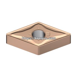
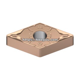
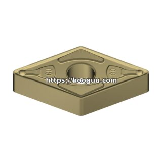
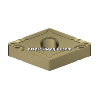
- Insert geometry: CNMG 120412 or SNMG 150612 with a heavy-duty chipbreaker for steel.
- Tool life target: 150-300 workpieces per edge for roughing; 500-1,000 per edge for finishing.
Internal and External Whirling for Pin Journals
Pin journals are offset from the crankshaft centerline by the crank throw (typically 35-55 mm for automotive engines). Two approaches are used:
- External whirling (pin milling): A rotating cutter head orbits the pin journal while the crankshaft rotates slowly. Cutting speed of 180-280 m/min with carbide inserts (SEKT or LNEX geometry). Feed per revolution of the cutter head: 0.2-0.5 mm. This process achieves Ra 1.6-3.2 um on pin journals.
- Internal whirling (pin turning): The crankshaft is held stationary and a single-point tool inside the cutter head machines the pin. Used for larger crankshafts where the cutter cannot orbit externally.
Fillet Rolling and Tooling for Fillet Radii
The fillet radius between the journal and the crank web is a critical fatigue feature. Machining must produce a smooth, consistent radius of 3-6 mm without sharp transitions:
- Fillet turning: A form tool or CNC-interpolated path machines the radius. Feed rate limited to 0.08-0.15 mm/rev to prevent chatter marks on the fillet surface.
- Fillet rolling: After machining, a hardened steel roller is pressed into the fillet at 15-30 kN force, inducing compressive residual stress of 400-700 MPa. This increases fatigue strength by 40-80%.
- Surface finish requirement: Ra 0.8-1.6 um on fillet radii before rolling; Ra 0.4-0.8 um after rolling.
Drilling Oil Passages
Crankshafts contain deep oil passages connecting main journals to pin journals. These holes are typically 5-8 mm diameter and 80-200 mm deep:
- Drill type: Solid carbide twist drills with through-coolant, 140-degree point angle.
- Cutting speed: 80-120 m/min at the drill periphery.
- Feed rate: 0.08-0.15 mm/rev.
- Coolant pressure: 40-80 bar through the drill for chip evacuation.
- Tool life: 200-500 holes per drill, depending on depth and cross-hole intersections.
- Peck cycle: Required for depths exceeding 15x diameter to clear chips; peck depth of 3-5x diameter.
Finish Grinding
After all turning and drilling operations, main and pin journals are finish-ground to final dimensions:
- Grinding wheel: Vitrified aluminum oxide (A46-K or A60-L grade), 600-900 mm diameter.
- Wheel speed: 35-45 m/s.
- Work speed: 60-120 RPM for cylindrical plunge grinding.
- Infeed rate: 0.005-0.015 mm/rev for rough grinding; 0.001-0.003 mm/rev for spark-out.
- Final tolerances: Main journals IT5 (typically 0.012 mm for 60 mm diameter); roundness within 0.003 mm.
- Surface finish: Ra 0.2-0.4 um, required for hydrodynamic bearing oil film formation.
Balancing Operations
Crankshafts must be dynamically balanced to within 5-15 g-cm of residual unbalance (depending on engine configuration). This is achieved by drilling or milling balance pads on the counterweights:
- Balance drilling: Holes of 8-16 mm diameter, 15-40 mm deep, positioned by the balancing machine CNC program.
- Material removal: 2-30 grams per pad, typically using solid carbide drills or flat-bottom end mills.
- Cycle time: 20-45 seconds per crankshaft for automated balancing machines.
Cycle Time and Cost Targets
For a high-volume automotive crankshaft, the total machining cycle time target is 4-8 minutes (rough turning, finish turning, drilling, and balancing combined across multiple machines). Tooling cost per crankshaft is typically $0.15-$0.40, with the total machining cost (including labor, overhead, and depreciation) of $3-$8 per crankshaft.
Conclusion
Forged steel crankshaft machining is a high-volume, cost-sensitive application where tool performance directly translates to production economics. Modern PVD-coated carbide grades, high-pressure coolant systems, and multi-axis CNC machines have reduced cycle times by 40-60% over the past two decades, but the fundamental challenge remains: producing sub-micron tolerances and mirror-finish surfaces on hard, abrasive forged steel at automotive production rates.
Shop Related Products at HOOGUU