Introduction: The Hard Steel Milling Challenge
Milling hardened steel — typically defined as materials in the 45–65 HRC range — remains one of the most demanding operations in modern machining. Unlike conventional steel milling, hard milling requires specialized insert grades, geometries, and cutting parameters that can withstand extreme thermal and mechanical loads while maintaining surface finish integrity. Whether you are finishing a die cavity, machining a tool steel mold core, or profiling hardened bearing seats, selecting the right milling insert directly impacts tool life, surface quality, and cycle time.
In this guide, we break down the critical factors for choosing milling inserts for hard steel applications (ISO H and hardened P materials), with a focus on three leading manufacturers: Sandvik Coromant, Seco Tools, and Kyocera. We cover grade selection, geometry considerations, and cutting parameters — backed by specific technical data and cross-brand comparisons.
Understanding Hard Steel Material Groups
Before selecting an insert, it is essential to understand the material characteristics you are dealing with. Hardened steels fall into several ISO application categories:
- ISO P (Steel, 45–55 HRC) — Hardened carbon and alloy steels used in shafts, gears, and bearing components. These materials exhibit moderate toughness but high abrasive wear potential.
- ISO H (Hardened Steel, 55–65 HRC) — Tool steels, die steels, and mold steels such as H13, D2, S7, and A2. Extreme hardness creates high cutting forces and significant edge stress.
- Stainless Hardened Steels — Precipitation-hardened grades like 17-4 PH that combine corrosion resistance with hardness up to 44 HRC.
The cutting zone temperatures in hard milling routinely exceed 800°C, and the workpiece surface can approach 600°C at the tool-chip interface. This makes substrate hardness and coating thermal stability the two most critical insert properties.
Key Factors in Hard Milling Insert Selection
1. Carbide Substrate and Grain Structure
For hard milling, the carbide substrate must offer a combination of high hot hardness (red hardness) and adequate transverse rupture strength (TRS). Ultra-fine and submicron grain sizes (0.4–0.8 μm) are preferred because they provide:
- Higher Vickers hardness at elevated temperatures (HRA 93–94 for premium grades)
- Improved edge strength to resist chipping on interrupted cuts
- Better wear resistance in the abrasive cutting zone
2. Coating Technology
The coating system is arguably the single most differentiating factor between insert grades for hard milling. Three coating architectures dominate:
- Single-layer TiAlN (Aluminum Titanium Nitride): Operating temperature up to 900°C. The aluminum oxide layer that forms during cutting provides exceptional thermal barrier properties. Common in finishing applications.
- Multi-layer TiAlN + TiN: Combines the thermal resistance of TiAlN with the lubricity and wear detection of a TiN top layer. Versatile for roughing to semi-finishing.
- Nano-structured or PVD-TiSiN: Silicon modification increases hardness to HV 35–38 GPa. Excellent for dry machining at very high cutting speeds. Used in high-performance finishing.
3. Insert Geometry
Hard milling demands specific geometries to manage cutting forces and heat:
- Lead angle: Smaller entering angles (15°–25°) reduce radial cutting forces and protect the thin cutting edge. Round inserts (RE type) distribute forces evenly across the edge.
- Edge honing: A light hone (0.02–0.05 mm) or specialized wiper geometry is critical. Too sharp an edge will chip; too blunt reduces surface finish.
- Number of cutting edges: For hard steel, 2-edge geometries are preferred over 4-edge designs because they provide greater chip space and lower cutting forces per edge.
4. Nose Radius and Wiper Flat
For finishing passes, inserts with wiper flats (bs type) or precision-ground nose radii (EN/EP type) achieve superior surface finishes (Ra 0.2–0.4 μm) compared to conventional radii. The wiper geometry effectively reduces the theoretical scallop height, allowing larger step-over distances without sacrificing surface quality.
Grade Comparison: Sandvik, Seco, and Kyocera for Hard Steel
The following table compares the leading insert grades from each manufacturer for hard steel milling applications. These grades represent each brand’s premium PVD-coated offerings for ISO P-hard and ISO H materials.
| Brand | Grade | Coating | Substrate Hardness (HRA) | Max Application Hardness | Primary Application | Recommended Vc Range |
|---|---|---|---|---|---|---|
| Sandvik Coromant | GC1010 | TiAlN (PVD) | 93.5 | 65 HRC | Finishing (ap ≤ 0.3 mm) | 120–200 m/min |
| Sandvik Coromant | GC1030 | Multilayer TiAlN/TiN (PVD) | 93.0 | 60 HRC | Semi-finishing (ap 0.3–1.0 mm) | 80–150 m/min |
| Seco Tools | SE412T | TiAlSiN (PVD, Nano) | 93.8 | 65 HRC | Finishing (ap ≤ 0.25 mm) | 130–220 m/min |
| Seco Tools | SE420T | TiAlN + TiN (PVD) | 93.2 | 62 HRC | Semi-finishing (ap 0.2–0.8 mm) | 90–160 m/min |
| Kyocera | PR1535M | TiAlN (PVD) | 93.4 | 62 HRC | Finishing & Semi-finishing | 100–180 m/min |
| Kyocera | PR1530 | Multilayer (PVD) | 93.0 | 58 HRC | Roughing (ap 0.5–2.0 mm) | 60–120 m/min |
Grade Selection Guidelines
For finishing (Ra ≤ 0.4 μm, ap ≤ 0.3 mm): The Seco SE412T and Sandvik GC1010 are the top performers. The SE412T’s nano-structured TiAlSiN coating offers the highest thermal stability, making it the preferred choice for continuous finishing passes on materials above 60 HRC. Sandvik GC1010 delivers excellent consistency and is widely available across insert geometries.
For semi-finishing (ap 0.3–1.0 mm): The Kyocera PR1535M offers the best balance of toughness and wear resistance for interrupted cuts in this range. Its moderate coating thickness prevents premature delamination on varying engagement conditions. Sandvik GC1030 is a strong alternative for stable spindle conditions.
For roughing hard steel (ap > 1.0 mm): Only the Kyocera PR1530 in this comparison handles roughing depths up to 2.0 mm in 55+ HRC materials. For more aggressive stock removal, consider CVD-coated grades or ceramic inserts from these manufacturers, though those are beyond the scope of this comparison.
Cutting Parameters: Detailed Reference Tables
Finishing Parameters (ap ≤ 0.3 mm, ae ≤ 0.5 mm)
| Workpiece Hardness | Insert Geometry | Vc (m/min) | fz (mm/tooth) | ap (mm) | ae (mm) | Achievable Ra |
|---|---|---|---|---|---|---|
| 45–50 HRC | Ball nose R4–R6 | 150–200 | 0.08–0.12 | 0.05–0.20 | 0.2–0.5 | 0.2–0.4 μm |
| 50–55 HRC | Ball nose R3–R5 | 130–170 | 0.06–0.10 | 0.05–0.15 | 0.15–0.4 | 0.2–0.5 μm |
| 55–60 HRC | Ball nose R2–R4 | 110–150 | 0.05–0.08 | 0.03–0.12 | 0.1–0.3 | 0.3–0.6 μm |
| 60–65 HRC | Ball nose R1.5–R3 | 80–120 | 0.04–0.07 | 0.02–0.10 | 0.08–0.25 | 0.4–0.8 μm |
Semi-Finishing Parameters (ap 0.3–1.0 mm)
| Workpiece Hardness | Insert Geometry | Vc (m/min) | fz (mm/tooth) | ap (mm) | ae (mm) |
|---|---|---|---|---|---|
| 45–50 HRC | Square/Shoulder, 45° lead | 120–160 | 0.10–0.15 | 0.3–0.8 | 3.0–6.0 |
| 50–55 HRC | Square/Shoulder, 45° lead | 100–140 | 0.08–0.12 | 0.3–0.6 | 2.5–5.0 |
| 55–60 HRC | Square/Shoulder, 25° lead | 80–120 | 0.06–0.10 | 0.2–0.5 | 2.0–4.0 |
| 60–65 HRC | Round insert R6–R8 | 60–100 | 0.05–0.08 | 0.2–0.4 | 1.5–3.0 |
Notes: fz values assume a 2-edge insert geometry. For 4-edge inserts, reduce fz by 20–30%. Coolant: air blast or MQL recommended for finishing; emulsion (8–12% concentration) acceptable for semi-finishing with adequate chip evacuation.
Tool Path Strategies for Hard Steel
Trochoidal Milling for Efficient Stock Removal
Trochoidal or circular interpolation milling has become the standard approach for removing significant stock from hardened materials. This technique maintains a constant chip thickness by keeping the arc of engagement small (typically 10–25% of the tool diameter), resulting in:
- Reduced radial cutting forces by 40–60% compared to conventional slot milling
- Lower tool temperature due to longer intervals between cutting engagements
- Up to 3× improvement in tool life for the same metal removal rate
When applying trochoidal milling with round inserts in 55–62 HRC steel, use Vc = 80–130 m/min, ae = 5–15% of Dc, and ap = 1.0–3.0 mm. The axial depth should be maximized to leverage the full cutting length while the radial engagement stays minimal.
Plunge Milling for Deep Cavities
For deep mold cavities where conventional side milling would require excessive tool overhang, plunge milling offers a rigid alternative. The axial cutting force in plunge milling is directed along the spindle axis, dramatically reducing deflection. Use a positive-rake insert (5°–10° axial rake) with a Z-axis feed of 0.05–0.12 mm/rev and step-over of 60–75% of the insert width.
Common Failure Modes and Mitigation
| Failure Mode | Visual Indicator | Root Cause | Mitigation Strategy |
|---|---|---|---|
| Nose wear / flank wear | Even wear land on flank face | Abrasive workpiece material, excessive Vc | Reduce Vc by 15–20%; switch to harder grade (SE412T or GC1010) |
| Chipping | Small fracture at cutting edge | Excessive fz, vibration, or interrupted cut | Reduce fz by 25%; increase ae slightly; ensure rigid workholding |
| Coating delamination | Peeling or flaking on rake face | Excessive cutting temperature beyond coating limit | Reduce Vc; verify coolant delivery; switch to higher-temperature coating |
| Plastic deformation | Deformed edge with no wear land | Workpiece too hard for grade, excessive ap | Upgrade to GC1010/SE412T; reduce ap to finishing range |
| Built-up edge (BUE) | Material adhesion on cutting edge | Low cutting speed, inadequate lubrication | Increase Vc; switch to MQL or air blast; use TiN top-layer grade |
Practical Selection Workflow
Follow this step-by-step process to select the optimal hard milling insert for your application:
- Identify the workpiece material and hardness. Start with the ISO classification (P-hard or H) and the actual HRC value. This narrows the grade range significantly.
- Determine the operation type. Finishing, semi-finishing, or roughing? This determines whether you need a dedicated finishing grade (thin PVD) or a tougher semi-finishing grade (multilayer PVD).
- Select the insert geometry. Match the lead angle to the feature geometry. Use ball nose for 3D surface finishing, square/shoulder for wall and pocket sidewalls, and round for roughing with trochoidal paths.
- Choose the brand and grade. Refer to the comparison table above. For finishing 60+ HRC, prioritize Seco SE412T. For general-purpose semi-finishing 50–60 HRC, Kyocera PR1535M offers excellent versatility. Sandvik grades provide the broadest geometry availability.
- Set initial parameters. Start at the lower end of the recommended Vc and fz ranges. Make the first cut and inspect the chip formation and surface finish before increasing parameters.
- Monitor and adjust. After the first 10–15 minutes of cutting, stop and inspect for the failure modes listed above. Adjust Vc, fz, or ap based on observed wear patterns.
Machining Common Hard Steels: Quick Reference
| Steel Grade | Typical HRC | ISO Class | Recommended Grade | Vc (Finishing) | Vc (Semi-finishing) |
|---|---|---|---|---|---|
| 1045 / C45 (hardened) | 50–55 | P | Sandvik GC1010 / Kyocera PR1535M | 140–180 | 100–140 |
| 4140 / 42CrMo4 (hardened) | 50–55 | P | Seco SE420T / Kyocera PR1535M | 130–170 | 90–130 |
| H13 (die steel) | 44–52 | P/H | Seco SE412T / Sandvik GC1030 | 150–190 | 110–150 |
| D2 (cold work die steel) | 58–62 | H | Seco SE412T / Sandvik GC1010 | 100–140 | 70–110 |
| S7 (shock-resistant tool steel) | 54–58 | H | Sandvik GC1030 / Kyocera PR1535M | 120–160 | 80–120 |
| A2 (air hardening tool steel) | 57–62 | H | Seco SE412T / Sandvik GC1010 | 110–150 | 75–115 |
| 17-4 PH (precipitation hardened) | 38–44 | P | Kyocera PR1530 / Seco SE420T | 160–210 | 120–170 |
| O1 (oil hardening tool steel) | 57–62 | H | Sandvik GC1010 / Seco SE412T | 100–140 | 70–100 |
Conclusion
Selecting the right milling insert for hard steel requires a systematic approach that considers workpiece hardness, operation type, insert geometry, and coating technology. The three manufacturers covered — Sandvik Coromant, Seco Tools, and Kyocera — each offer competitive grades with distinct strengths:
- Seco Tools SE412T leads in pure finishing performance on the hardest materials (60–65 HRC) thanks to its nano-structured TiAlSiN coating.
- Sandvik Coromant GC1010 delivers the broadest insert geometry portfolio with consistent finishing results across all hard steel types.
- Kyocera PR1535M excels in semi-finishing applications with superior edge toughness, making it ideal for interrupted cuts and variable-engagement toolpaths.
Start with the parameter tables in this guide, verify with a test cut, and adjust based on observed tool wear patterns. For hard milling, the difference between a well-selected and poorly-selected insert often means 2–3× the tool life and significantly better surface quality — translating directly to lower cost-per-part and higher throughput.
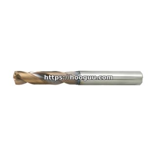
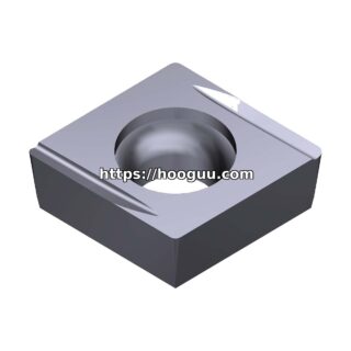
Shop Related Products at HOOGUU