
Interrupted Cutting Strategy: How to Machine Splines and Keyways Without Chipping
Interrupted cutting—where the tool repeatedly enters and exits the workpiece during each revolution or pass—is one of the most punishing conditions a cutting tool can face. Every entry is an impact event; every exit is a thermal shock. The cyclic loading accelerates fatigue cracking in the cutting edge, and the repeated thermal cycling from hot (in cut) to cold (out of cut) promotes coating delamination and substrate fracture. Splines, keyways, cross-holes, splined shafts, and gear teeth all create interrupted cut conditions that require a fundamentally different approach from continuous cutting.
The Physics of Interrupted Cutting
In a continuous turning operation, the cutting edge reaches thermal equilibrium within 5–10 seconds. The temperature stabilizes, cutting forces remain constant, and the tool wears predictably through gradual flank wear. In an interrupted cut, the tool never reaches equilibrium. Each engagement produces a thermal spike as the cutting edge contacts the workpiece, followed by rapid cooling as the tool exits. This thermal cycling creates micro-cracks in the coating and substrate—a failure mechanism known as thermal fatigue or comb cracking.
Simultaneously, the mechanical impact at entry generates stress waves that propagate through the cutting edge. If the impact energy exceeds the substrate’s fracture toughness, micro-chips break away from the cutting edge. After several hundred impacts, these micro-chips coalesce into a visible fracture that renders the tool useless.
Common Interrupted Cut Applications
| Application | Type of Interruption | Severity | Primary Failure Mode |
|---|---|---|---|
| Turning splined shafts | Periodic (every spline tooth) | High | Edge chipping, comb cracking |
| Milling keyways | Cyclic (each flute entry/exit) | Moderate to high | Flute fracture |
| Turning parts with cross-holes | Periodic (once per revolution) | Moderate | Notch wear, edge chipping |
| Facing cast parts with sand inclusions | Random | Variable | Catastrophic chipping |
| Machining gear teeth (gear hobbing/shaping) | Continuous cyclic | High | Flank chipping, pitting |
| Turning slotted or keyed bores | Periodic | Moderate to high | Edge breakdown |
Tool Selection for Interrupted Cuts
The key principle is prioritizing toughness over hardness. In interrupted cutting, a harder tool that chips is worse than a tougher tool that wears faster but survives.
Carbide Grade Selection
- Substrate: Use a tough, medium-grain (1.0–1.5 µm) or coarse-grain (1.5–3.0 µm) carbide substrate with high cobalt content (8–12%). Fine-grain substrates offer higher hardness but lower fracture toughness—they will chip in interrupted cuts.
- Coating: PVD coatings (TiAlN, AlCrN) are strongly preferred over CVD coatings for interrupted cuts. PVD coatings are thinner (2–4 µm vs. 10–20 µm for CVD), more adherent, and applied at lower temperatures, which preserves the substrate’s toughness. CVD coatings, while harder and more wear-resistant, are brittle and tend to spall under impact loading.
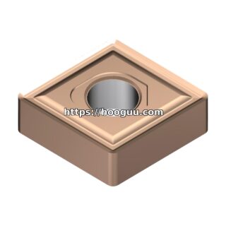
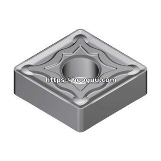
- Edge preparation: A T-land or chamfer (20° × 0.10–0.20mm) strengthens the cutting edge and distributes the impact force over a larger area. Honing the edge to a radius of 15–30 µm further prevents micro-chipping.
Insert Geometry
- Negative rake angles: While positive rake reduces cutting forces in continuous cutting, negative rake (-5° to -15°) strengthens the edge for interrupted work. The wedge angle is larger, providing more material behind the cutting edge to resist impact.
- Thick insert cross-sections: Use thicker inserts (e.g., 4.76mm or 6.35mm instead of 3.18mm) for increased bulk strength.
- Round inserts: For severely interrupted cuts, round inserts (RCGT, RNGN) distribute the impact across a continuously varying contact point, preventing the development of localized wear notches.
Real-World Example: Turning an Involuate Spline Shaft
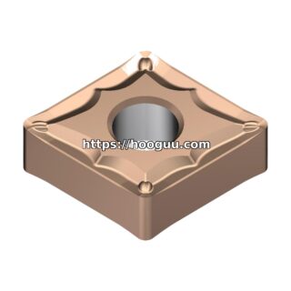
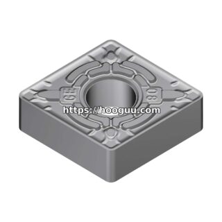
A powertrain shop was turning the bearing journal diameters on a 42CrMo4 spline shaft (280 HB). The shaft had 16 involute spline teeth, meaning the turning tool experienced 16 impacts per revolution. Initial tooling was a CNMG 120408 with a standard positive-rake chipbreaker at Vc = 180 m/min, f = 0.25 mm/rev, ap = 2.0mm. Tool life was 12 parts before edge chipping forced a change.
The solution involved three changes:
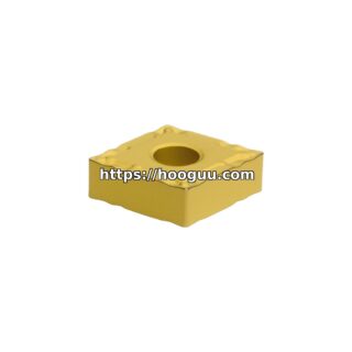
- Switched to a Korloy CNMG 120408 insert with a tough PVD-coated grade (NC3125), featuring a 12% cobalt substrate and 3-micron AlTiN PVD coating.
- Applied a 20° × 0.15mm T-land edge preparation with a 25-micron hone.
- Reduced cutting speed to Vc = 140 m/min (lower speed reduces impact energy per tooth) and increased feed slightly to f = 0.28 mm/rev (thicker chip provides a cushioning effect at entry).
Tool life improved to 65 parts per edge—a 442% improvement. The slight speed reduction was more than offset by the elimination of unplanned tool changes and scrapped parts from chipped edges.
Cutting Parameter Guidelines for Interrupted Cuts
| Parameter | Continuous Cut | Interrupted Cut | Reason |
|---|---|---|---|
| Cutting speed (Vc) | High (per catalog) | Reduce by 20–30% | Lower impact energy per engagement |
| Feed rate (f) | Moderate | Maintain or slightly increase | Thicker chip cushions the cutting edge at entry |
| Depth of cut (ap) | Per requirement | Reduce by 15–25% | Lower radial forces reduce impact stress |
| Coolant | Flood or high-pressure | Dry or air blast preferred | Avoid thermal shock from cold coolant on hot-then-cold edge |
| Entry/exit strategy | Not applicable | Chamfer workpiece edges, ramp entry | Gradual engagement reduces peak impact force |
Milling Keyways: A Special Case
Milling keyways on a shaft or in a bore creates severe interrupted cutting conditions as each flute enters and exits the slot. Key strategies include:
- Unequal flute spacing: End mills with unequal flute spacing break the harmonic frequency of the impacts, preventing resonance and chatter. A 4-flute cutter with 90° spacing creates impacts at a single frequency; unequal spacing (e.g., 85°/95°/85°/95°) spreads the energy across multiple frequencies.
- Helical ramp entry: Instead of plunging straight into the slot, program a helical ramp that gradually engages the cutter. This converts the initial impact into a smooth entry.
- Climb milling only: In climb milling, the chip thickness decreases from maximum to zero during each tooth engagement. The tooth exits the cut with a thin chip, reducing the exit burr and preventing edge damage.
- Slot width optimization: If the keyway width allows, use a cutter that is 70–80% of the slot width and mill in multiple passes. This avoids full-width engagement and reduces the severity of each interruption.
Korloy Solutions for Interrupted Cutting
Korloy’s NC3125 and NC3225 insert grades are specifically engineered for interrupted cutting conditions. They combine a tough, high-cobalt substrate with PVD AlTiN coating to deliver the fracture resistance that interrupted cuts demand. Their turning and milling inserts are available with T-land edge preparations, controlled hones, and round geometries suitable for splines, keyways, and cross-hole applications. Find the right interrupted-cut tooling for your application at hooguu.com.
Conclusion
Interrupted cutting is unavoidable in many machining applications, but tool failure is not. By selecting tough carbide grades with PVD coatings, applying appropriate edge preparations, reducing cutting speed, and optimizing the entry and exit conditions, shops can machine splines, keyways, and cross-holes with predictable tool life and consistent quality. The key is recognizing that interrupted cutting demands a different philosophy than continuous cutting—prioritize toughness, cushion the impact, and avoid thermal shock.
Shop Related Products at HOOGUU