

Invar 36 and Kovar Machining: Korloy Tools for Low Thermal Expansion Alloys
Introduction to Low Thermal Expansion Alloys
Invar 36 and Kovar represent a specialized class of iron-nickel alloys selected not for their strength or corrosion resistance, but for their extraordinary dimensional stability across temperature changes. These materials are machined for applications where thermal expansion would be catastrophic to function: precision optics, satellite structures, laser systems, glass-to-metal seals, and metrological equipment.
The irony of machining these materials is significant: they are chosen specifically because they do not change dimensions with temperature, yet the machining process itself can introduce residual stresses that cause dimensional instability far exceeding any thermal expansion. This creates a unique set of requirements that prioritize low cutting forces, minimal heat generation, and careful process planning over productivity metrics.
Material Properties and Machining Characteristics
Invar 36 (Fe-36Ni, UNS K93600)
Invar 36 contains approximately 36% nickel in an iron matrix, resulting in a coefficient of thermal expansion (CTE) of approximately 1.2 x 10^-6 per degree Celsius at room temperature, roughly one-tenth that of standard steel. The material has a hardness of approximately 150-180 HB in the annealed condition and tensile strength of 480-520 MPa. It is fully austenitic at all temperatures below its Curie point.
Applications include optical bench structures, telescope frames, satellite structural components, precision tooling masters, shadow masks for displays, cryogenic tank components, and composite tooling for aerospace layup.
Kovar (Fe-29Ni-17Co, UNS K94610)
Kovar contains approximately 29% nickel and 17% cobalt, giving it a CTE that closely matches borosilicate glass and certain ceramics (approximately 5.1 x 10^-6 per degree Celsius). This thermal expansion matching is critical for creating hermetic glass-to-metal and ceramic-to-metal seals used in electronic packaging, vacuum feedthroughs, and high-reliability connectors.
Kovar is slightly harder than Invar 36 (typically 160-200 HB) due to the cobalt addition and tends to work-harden more aggressively during machining. Its applications include microelectronic packages, RF connectors, hermetic headers, and power semiconductor housings.
Common Machining Challenges
Both Invar 36 and Kovar are gummy nickel-iron alloys that share several machining difficulties:
- Extreme gumminess: High nickel content produces long, stringy chips and aggressive built-up edge, similar to pure nickel but somewhat mitigated by the iron content
- Work-hardening: Both materials work-harden rapidly (surface hardness can increase 30-50% from machining), creating a hard skin that damages subsequent cutting passes if DOC is insufficient
- Dimensional sensitivity: Residual stresses from machining cause distortion during and after cutting, potentially negating the material’s low-CTE advantage
- Tool adhesion: Strong tendency for workpiece material to weld to the cutting edge, degrading surface finish and accelerating wear
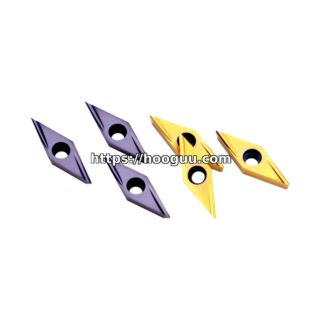
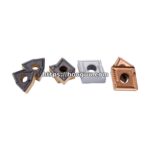
Korloy Tool Selection
Primary Grade: PC9530
Korloy PC9530 is the recommended grade for both Invar 36 and Kovar machining. The thin PVD coating maintains the sharp edge necessary to shear these gummy materials while providing sufficient wear resistance for the moderate cutting speeds used. The tough substrate accommodates the varying forces that result from inconsistent chip formation inherent to high-nickel alloys.
The key advantage of PC9530 in this application is its ability to maintain edge sharpness over time. As discussed below, sharp edges are essential not only for surface finish but for minimizing the cutting forces that introduce the residual stresses these applications cannot tolerate.
Chipbreaker Selection: NM or MM
The NM chipbreaker (light finishing geometry) is preferred for finishing operations where surface integrity and minimal residual stress are paramount. Its highly positive rake angle reduces cutting forces by 20-30% compared to standard geometries, directly reducing the magnitude of residual stresses imparted to the workpiece.
The MM chipbreaker (medium geometry) provides better chip control during roughing operations where chip management becomes the priority. The slightly more aggressive chip control groove helps break the otherwise continuous chips produced by these alloys, though cutting forces are moderately higher than the NM geometry.
Geometry: Positive Rake, Light DOC
Positive geometry inserts are mandatory for Invar and Kovar. The reduced cutting forces from positive rake directly serve the primary requirement of these applications: dimensional stability. Every newton of unnecessary cutting force translates to residual stress that may cause the part to move after machining, potentially by amounts that exceed the entire functional tolerance of the component.
Light depths of cut (0.3-1.5mm roughing, 0.1-0.5mm finishing) further reduce forces. While this reduces material removal rates, the alternative (heavy cuts followed by extensive stress-relief heat treatments) is rarely more economical when the full process cost is considered.
Cutting Parameter Recommendations
| Alloy | Key Property | Korloy Grade | Chipbreaker | Turning Speed (m/min) | Feed (mm/rev) | DOC (mm) | Notes |
|---|---|---|---|---|---|---|---|
| Invar 36 – roughing | CTE: 1.2 x 10^-6/C | PC9530 | MM | 40-60 | 0.12-0.20 | 0.5-1.5 | Leave 0.5mm+ for finishing after stress relief |
| Invar 36 – finishing | CTE: 1.2 x 10^-6/C | PC9530 | NM | 45-60 | 0.05-0.12 | 0.1-0.5 | Sharp edge critical; minimal force |
| Invar 36 – milling | CTE: 1.2 x 10^-6/C | PC9530 | MM | 20-35 | 0.06-0.12 mm/tooth | 0.3-1.0 | Climb milling only; avoid slotting |
| Kovar – roughing | CTE: 5.1 x 10^-6/C | PC9530 | MM | 30-50 | 0.10-0.18 | 0.5-1.5 | More work-hardening than Invar; don’t dwell |
| Kovar – finishing | CTE: 5.1 x 10^-6/C | PC9530 | NM | 35-55 | 0.05-0.10 | 0.1-0.4 | Critical for seal surfaces; Ra < 0.4 target |
| Kovar – milling | CTE: 5.1 x 10^-6/C | PC9530 | MM | 20-40 | 0.05-0.10 mm/tooth | 0.3-1.0 | Minimize radial engagement for thin walls |
| Super Invar (Fe-31Ni-5Co) | CTE: 0.6 x 10^-6/C | PC9530 | NM | 30-50 | 0.05-0.15 | 0.3-1.0 | Most dimensionally critical; lightest cuts |
Dimensional Stability: The Overriding Concern
Why These Parts Need Stress Relief Between Operations
The entire purpose of using Invar or Kovar is dimensional stability. Machining-induced residual stresses directly undermine this purpose. A component machined from Invar 36 with poor process control can exhibit dimensional changes of 10-50 micrometers over time as stresses relax. This completely negates the benefit of a material with near-zero thermal expansion if the application requires micrometer-level stability.
Best practice for precision Invar/Kovar components involves multiple machining and stress-relief cycles:
- Rough machining: Remove bulk material, leaving 0.5-1.0mm per side for finishing
- Stress relief: Thermal cycle at 315-370 degrees Celsius for Invar, 500-600 degrees Celsius for Kovar, in vacuum or inert atmosphere to prevent oxidation
- Semi-finish machining: Remove stress-relief distortion, leave 0.1-0.3mm for final finish
- Second stress relief: Same thermal cycle (may be omitted for less critical applications)
- Finish machining: Final dimensions with minimum possible cutting forces using NM chipbreaker geometry
This multi-step process significantly increases manufacturing time and cost but is essential for components where dimensional stability is the primary functional requirement.
Minimizing Cutting Force to Preserve Stability
Every aspect of the tooling selection for Invar/Kovar should prioritize force reduction:
- Positive rake geometry (NM chipbreaker) reduces forces by 25-35% versus negative geometry
- Sharp edges (minimal hone, maximum 0.02mm radius) prevent ploughing that generates subsurface stress
- Small nose radius (0.4mm for finishing) reduces the passive force component
- Light depth of cut limits the deformation zone depth
- Adequate cutting speed (within recommended range) ensures proper shearing rather than tearing
Coolant Strategy
Flood coolant is mandatory for both Invar and Kovar machining. The coolant serves multiple purposes: thermal control to prevent localized heating that could cause in-process distortion, lubrication to reduce cutting forces (directly supporting dimensional stability), and chip flushing to prevent re-cutting of work-hardened chips.
Water-soluble coolant at 8-10% concentration with good lubricity characteristics is recommended. Coolant pressure of 20-40 bar through directed nozzles or through-tool delivery helps manage the long, stringy chips these materials produce.
For Kovar components destined for glass-to-metal sealing, surface cleanliness after machining is critical for achieving good seal adhesion. The coolant must be fully removable through standard cleaning processes (ultrasonic cleaning in appropriate solvents). Avoid coolants with high residue or sulphur-bearing EP additives that could contaminate the sealing surface.
Special Considerations for Thin-Walled Parts
Many Invar and Kovar components feature thin walls (optical bench structures, electronic packages). Machining thin sections in these gummy, work-hardening materials requires particular care:
- Reduce radial engagement in milling to limit deflection forces
- Use multiple light passes rather than single deep cuts
- Consider climb milling exclusively to minimize entry forces
- Support thin walls with appropriate fixturing or fill materials
- Allow for spring-back between roughing and finishing operations
For walls below 1mm thickness, cutting speeds should be reduced to the lower end of recommendations to minimize vibration and ensure the tool maintains control throughout the cut.
Tool Life and Economics
Expected tool life with PC9530 at recommended parameters: approximately 15-25 minutes per edge for turning, 20-30 minutes for milling. Tool life is primarily limited by adhesive wear and progressive BUE that degrades surface finish before catastrophic failure occurs. Replace inserts based on surface finish degradation rather than waiting for complete edge failure.
The relatively low cutting speeds and light depths of cut used for these materials mean that cycle times are inherently longer than for comparable steel components. This is accepted as the cost of maintaining the dimensional integrity that justifies using these expensive specialty alloys.
Contact Hooguu for specialized Korloy tooling recommendations for your Invar or Kovar application, including guidance on process planning for dimensionally critical components.
Shop Related Products at HOOGUU