

The Most Frustrating Problem in CNC Machining
You change the insert, run the first part, and the surface finish is terrible. The previous insert produced Ra 0.8 um parts all day, and the new insert gives Ra 2.5-4.0 um on the very first piece. This scenario plays out daily in machine shops worldwide, and the root cause is almost always runout, seating problems, or setup errors rather than the insert itself. Understanding and eliminating these causes can reduce scrap rates by 60-80% and prevent unnecessary insert and tooling replacement.
What Is Runout and How It Affects Surface Finish
Runout is the deviation of the cutting edge from its theoretical position as the tool rotates (in milling) or as the workpiece rotates (in turning). It causes uneven chip thickness across the cutting edge, leading to vibration, chatter, and poor surface finish.
Sources of Runout in Turning
- Insert seating error: If the insert is not seated flat in the pocket (due to chips, dirt, or a damaged seat), the cutting edge tilts. A 0.02 mm chip under one corner of a CNMG 120408 insert changes the effective cutting edge position by 0.02-0.04 mm, enough to produce visible feed marks on the workpiece.
- Tool holder clamping runout: Worn clamp screws, deformed clamp arms, or broken chipbreaker pins allow the insert to shift under cutting forces. Top-clamp style holders (ISO P-type) typically have less runout than screw-clamp (ISO S-type) or lever-clamp (ISO C-type) holders.
- Tool holder shank runout: The tool holder shank itself may have runout from wear in the turret pocket or taper. A CAT40/BT40 tool holder with 0.005 mm gauge line TIR is acceptable; above 0.010 mm is a problem for finishing operations.
Sources of Runout in Milling
- Collet runout: ER collets (ER25, ER32, ER40) have typical runout of 0.005-0.015 mm at the nut face, which increases to 0.010-0.030 mm at 3x diameter overhang. For finish milling, this translates to uneven chip loads: one flute may take 50% more material than the others.
- Shrink-fit and hydraulic holders: These premium holders deliver 0.002-0.005 mm TIR at the gauge line, 3-5x better than standard collet chucks. The surface finish improvement is dramatic: Ra 0.4-0.8 um with shrink-fit vs Ra 1.2-2.0 um with a worn ER collet at the same parameters.
- End mill shank tolerance: A solid carbide end mill with an h6 shank (tolerance: 0 to -0.007 mm for 10 mm diameter) may have up to 0.007 mm clearance in the collet, contributing to runout. Precision ground h5 shanks (0 to -0.005 mm) reduce this clearance.
Diagnosing Runout: Measurement Methods
Static Measurement
- Dial indicator: Mount a 0.001 mm resolution dial indicator on the machine column and indicate the cutting edge or tool shank while rotating the spindle by hand. Record TIR (total indicator reading) at the cutting edge.
- Acceptable runout for finishing: Less than 0.005 mm TIR at the cutting edge for Ra below 0.8 um; less than 0.010 mm for Ra below 1.6 um.
- Non-contact laser measurement: Systems like Blum MicroComp or Renishaw NC4 measure tool runout at full spindle speed (up to 42,000 RPM), revealing dynamic runout that static measurement cannot detect.
Dynamic (In-Spindle) Measurement
Static runout can be misleading because thermal growth, centrifugal force, and clamping force variation change the tool position at operating speed:
- Spindle growth: A spindle that runs at 15,000 RPM may grow 0.010-0.030 mm axially and shift 0.003-0.008 mm radially due to bearing thermal expansion.
- Centrifugal expansion: Tool holders expand radially at high RPM. A CAT40 holder at 15,000 RPM may expand 0.002-0.005 mm at the flange, changing the clamping force and tool position.
- Measurement solution: Use a non-contact laser tool setter to measure the tool at operating speed after a 3-5 minute warm-up cycle.
Fixes for Insert Seating and Clamping Problems
1. Clean the Pocket Before Every Insert Change
- Use compressed air (minimum 6 bar) and a nylon brush to remove all chips and debris from the insert pocket, clamp, and screw.
- Inspect the pocket seat with a magnifying glass or borescope for nicks, burrs, or built-up material. A 0.01 mm burr on the seat can tilt the insert enough to affect surface finish.
- Apply a thin film of anti-seize compound (copper or nickel-based) to the clamp screw threads to ensure consistent clamping torque.
2. Use Consistent Clamping Torque
- Tighten the clamp screw with a torque wrench to the manufacturer’s specification (typically 3-6 Nm for CNMG 1204 inserts, 8-14 Nm for larger SNMG 1506 inserts).
- Under-torquing allows the insert to shift under cutting forces, causing chatter and dimensional errors.
- Over-torquing can strip the screw threads or deform the clamp, also causing insert movement.
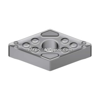
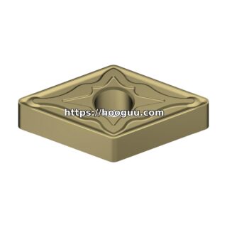
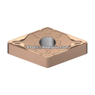
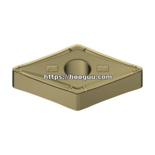
3. Verify Insert Geometry
- Nose radius: Confirm the correct nose radius is installed. A 0.4 mm nose radius produces Ra approximately 0.4-0.8 um at 0.15 mm/rev feed; a 0.8 mm nose radius produces Ra approximately 0.2-0.4 um at the same feed.
- Wiper geometry: If the previous insert had a wiper flat and the replacement does not (or vice versa), surface finish will change dramatically. Wiper inserts (e.g., Sandvik MW chipbreaker, Kennametal Wiper style) have a secondary flat that “wipes” the feed marks from the previous cutting edge pass.
- Insert hand: Right-hand vs left-hand inserts produce different chip flow directions and may require adjustment of the toolpath or feed direction.
Machine Condition Issues
Spindle Bearing Wear
Worn spindle bearings increase both static and dynamic runout. Signs include:
- Increasing runout trend over weeks or months (measured during regular PM checks).
- Higher spindle noise or vibration at specific speeds.
- Poor surface finish that varies with spindle speed (worse at resonant frequencies).
- Action: Replace spindle bearings when TIR exceeds 0.005 mm at the gauge line. Cost: $5,000-$15,000 for a standard VMC spindle rebuild.
Turret or Tool Post Looseness
- On CNC lathes, turret clamping mechanisms (Hirth coupling, curvic coupling, or bolt-clamp) can wear and allow micro-movement during cutting.
- Test: Mount a test bar in the turret and push/pull with a dial indicator. Movement exceeding 0.005 mm indicates worn coupling teeth or loose clamping bolts.
- Action: Regrind or replace the Hirth/curvic coupling. Typical cost: $2,000-$8,000 depending on turret size.
Way and Ballscrew Backlash
- Excessive backlash (above 0.005 mm) in the X or Z axis causes dimensional errors during direction changes, visible as steps or lines on turned surfaces.
- Test: Use a laser interferometer or ballbar to measure backlash and positioning accuracy.
- Action: Adjust ballscrew preload, replace worn thrust bearings, or upgrade to linear scale closed-loop feedback.
Process Verification After Tool Change
Establish a standard procedure for every insert change:
- Clean the pocket thoroughly with air and brush.
- Inspect the seat and clamp for damage.
- Install the new insert and torque the clamp screw.
- Verify tool offset (X and Z for turning; length and diameter for milling) by probing or test cut.
- Run a single part and measure surface finish and dimensions.
- If finish is out of spec, check runout before changing parameters or replacing the insert.
Conclusion
Poor surface finish after a tool change is almost never caused by the insert itself. The root causes are insert seating errors, tool holder runout, machine condition issues, or incorrect insert geometry selection. By implementing a disciplined tool change procedure that includes pocket cleaning, torque verification, runout measurement, and first-part inspection, shops can eliminate the majority of surface finish problems and reduce scrap rates by 60-80%. The investment in precision tool holders (shrink-fit or hydraulic) and regular machine condition monitoring pays for itself within weeks through reduced scrap and rework.
Shop Related Products at HOOGUU