
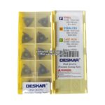
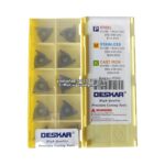
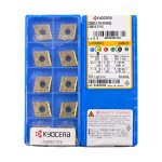
Why Stainless Steel Milling Behaves Differently
Stainless steel is not a single material — it is a family of alloys whose common trait is a chromium-rich passive oxide layer. For the machinist, that layer is the least of the problems. The real difficulties come from three coupled properties: high strain hardening rate, low thermal conductivity (roughly 15–16 W/m·K for austenitic grades versus 45–50 W/m·K for plain carbon steel), and a high tendency to adhere to the cutting edge. Together they produce the classic stainless milling failure modes: built-up edge, work-hardened skin, notch wear at the depth-of-cut line, and rapid flank wear driven by heat that cannot escape through the chip.
Because the heat stays in the tool, edge temperatures in stainless milling routinely run 150–250 °C higher than in carbon steel at the same cutting speed. That single fact drives almost every selection decision in this guide: choose a grade that tolerates heat, choose a geometry that cuts rather than rubs, and keep the cutter engaged so the edge is never allowed to dwell in the cut.
Stainless Steel Families and What Each One Demands
Before choosing a grade or a cutter, identify which stainless family is on the table. The machining window between 303 free-machining austenitic and 904L super-austenitic is a factor of four in cutting speed.
| Family | Typical Grades | Core Hardness | Machinability vs 1045 | Dominant Problem |
|---|---|---|---|---|
| Free-machining austenitic | 303, 303Se, 416 | 150–180 HB | 55–70% | Chip control; sulfur embrittlement of edges |
| Standard austenitic | 304, 304L, 316, 316L, 321 | 150–200 HB | 40–50% | Work hardening, built-up edge, adhesive wear |
| Martensitic / precipitation | 420, 440C, 17-4PH (630) | 200–300 HB / 28–38 HRC | 30–45% | Notch wear, thermal cracking in interrupted cuts |
| Duplex | 2205, 2507, LDX 2101 | 230–290 HB | 25–35% | High cutting forces, severe work hardening, edge chipping |
| Super-austenitic / Ni-alloyed | 904L, 254SMO, 6Mo | 180–220 HB | 15–25% | Heat concentration, rapid crater and flank wear |
The practical consequence: a parameter table built for 304 will destroy tools in 2205 duplex, and will leave 40% of the available productivity on the table in 303. Always scale cutting data by family first, then by hardness and operation.
Insert Grade Selection: PVD, CVD or Uncoated
For stainless milling, PVD-coated fine-grain carbide is the default. CVD coatings carry tensile residual stress and a thick Al2O3 layer that is excellent for turning at high temperature but prone to spalling under the repeated mechanical shocks of milling. PVD TiAlN or AlTiN coatings, deposited at 450–500 °C, leave the substrate in compression and produce a thin (2–4 µm), hard, smooth layer that resists adhesive wear without weakening the edge.
| Grade Type | Coating | Best Application | Typical Vc (m/min) | Limitation |
|---|---|---|---|---|
| PVD TiAlN, fine grain | 2–4 µm, multilayered | 304/316 general milling, wet | 120–180 | Not for heavy interrupted cuts in duplex |
| PVD AlTiN, micro-grain | 3–5 µm | 17-4PH, 420, harder stainless | 90–150 | Oxidation limit ~900 °C |
| PVD TiCN / TiN multilayer | 2–3 µm | Finishing, low speed, small cutters | 80–140 | Lower hot hardness |
| Uncoated, sharp positive | None | 303, 416, aluminium-bronze, small-diameter end mills | 60–120 | Short life at high speed |
| CVD thick Al2O3 | 8–12 µm | Rough turning only — avoid in milling | — | Spalling, thermal crack propagation |
Substrate choice matters as much as coating. Look for a cobalt content of 8–10% with a grain size of 0.5–0.8 µm: enough toughness to survive the entry shock of a face mill, enough hardness to resist the abrasive oxide layer that forms on the workpiece surface.
Geometry: Sharp, Positive and Never Rubbing
Stainless steel punishes any geometry that rubs. A honed, negative-rake insert that works well in cast iron will generate a work-hardened layer within a few passes and then fail by notch wear at the depth-of-cut line. The rules are:
- Positive rake (8–15°) to reduce cutting force and heat generation. In duplex and 904L, go to the upper end.
- Sharp, light-honed edge — a T-land of 0.05–0.10 mm × 15–20° is enough. Heavy honing (0.15 mm+) doubles thrust force.
- Open chipbreaker for roughing (0.3–0.5 mm geometry range for fz 0.15–0.25 mm), tighter for finishing. A closed breaker in stainless will pack chips and stall.
- High lead angle (45° or 90° shoulder mills on the periphery) to thin the chip. At 45°, effective chip thickness is 0.71 × fz; at 10° approach, 0.17 × fz.
- Variable helix / unequal pitch on solid carbide end mills to suppress chatter in thin-walled 316L parts.
A 45° face mill combined with a positive axial rake is the single most productive roughing configuration for austenitic stainless: it transfers the cutting force axially into the spindle rather than radially into the workpiece, which matters on flexible fixtures.
Cutting Parameters by Family and Operation
The tables below assume a PVD TiAlN-coated carbide insert, flood coolant, a rigid 50-taper machine, and a cutter with a positive rake. Reduce Vc by 20% for small-diameter solid carbide tools or long overhangs, and increase fz by 15–20% if the radial engagement is below 30% of diameter (chip thinning compensation).
Face Milling (45° lead, Dc 50–125 mm)
| Material | Vc (m/min) | fz (mm/tooth) | ap (mm) | ae (% of Dc) | RPM for Dc 80 | Feed (mm/min) |
|---|---|---|---|---|---|---|
| 303 / 416 | 180–240 | 0.15–0.25 | 1.5–4.0 | 60–75% | 716–955 | 1100–1900 |
| 304 / 316L | 130–180 | 0.12–0.20 | 1.5–3.5 | 60–70% | 517–716 | 750–1430 |
| 17-4PH (H1150) | 100–140 | 0.10–0.16 | 1.0–3.0 | 50–65% | 398–557 | 480–1070 |
| 2205 duplex | 60–90 | 0.08–0.14 | 1.0–2.5 | 40–55% | 239–358 | 290–700 |
| 904L / 254SMO | 45–70 | 0.08–0.12 | 0.8–2.0 | 35–50% | 179–279 | 215–500 |
Square Shoulder and Slotting (90° lead, solid carbide or indexable)
| Material | Vc (m/min) | fz (mm/tooth) | ap (mm) | ae (mm) | Note |
|---|---|---|---|---|---|
| 304 / 316L | 110–160 | 0.05–0.10 | 0.5–1.5 × Dc | 0.3–0.5 × Dc | Ramp 2–3° instead of plunging |
| 17-4PH | 80–120 | 0.04–0.08 | 0.4–1.0 × Dc | 0.25–0.4 × Dc | Reduce ae before reducing Vc |
| 2205 duplex | 50–80 | 0.04–0.07 | 0.3–0.8 × Dc | 0.2–0.35 × Dc | Climb mill only; never dwell |
Drilling and Tapping Reference
| Operation | 304 / 316L | 17-4PH | 2205 |
|---|---|---|---|
| Solid carbide drill, Vc (m/min) | 60–90 | 45–65 | 35–50 |
| Drill feed (mm/rev), Ø8 mm | 0.10–0.15 | 0.08–0.12 | 0.06–0.10 |
| Peck depth | 1.0–1.5 × D | 0.8–1.0 × D | 0.5–0.8 × D |
| Tap cutting speed (m/min) | 8–15 | 5–10 | 3–6 |
| Tap thread engagement limit | 1.5 × D | 1.5 × D | 1.0–1.5 × D |
Worked Example: 316L Manifold Block
A 316L block, 250 × 180 × 90 mm, machined on a 40-taper VMC with flood coolant. Roughing with an Ø80 mm, 45° face mill, 6 inserts, positive rake, PVD TiAlN grade.
- Vc = 150 m/min → n = 597 rpm, round to 600 rpm.
- fz = 0.15 mm → vf = 600 × 6 × 0.15 = 540 mm/min.
- ap = 2.5 mm, ae = 55 mm (69% of Dc) → material removal rate 74 cm³/min.
- Spindle power check: specific cutting force for 316L ≈ 2,200 N/mm². Power at the cut = kc × MRR / 60,000 = 2,200 × 74,250 / 60,000 ≈ 2.7 kW; at 80% spindle efficiency that is 3.4 kW — comfortably inside a 15 kW machine.
If edge life falls below 20 minutes, reduce Vc to 130 m/min before touching the feed. In stainless, speed is the life killer; feed is the work-hardening killer. Never reduce fz below 0.10 mm/tooth to “be gentle” — that is exactly what produces a hardened skin and notch wear.
Coolant Strategy
Stainless milling is a wet process. High-pressure coolant (HPC) at 40–70 bar through the tool delivers two benefits: it breaks the chip at the tool face and it removes heat from the insert rather than the workpiece.
| Operation | Pressure | Flow | Concentration |
|---|---|---|---|
| Face milling, roughing | 10–20 bar | 30–60 L/min | 6–8% |
| Shoulder milling / pocketing | 20–40 bar | 20–40 L/min | 7–9% |
| Deep pockets, duplex | 50–70 bar | 15–30 L/min | 8–10% |
| Through-tool drilling | 40–70 bar | 10–25 L/min | 8–10% |
Avoid dry milling of austenitic stainless except in finishing passes with air blast on thin-wall parts where thermal shock is the dominant failure. If you must run dry, drop Vc by 30% and accept 40–50% of wet tool life.
Tool Path Strategy: Keep the Edge Loaded
Stainless work-hardens the moment the edge stops cutting and starts rubbing. Three tool path rules prevent that:
- Climb mill whenever the machine has backlash-free ball screws. Conventional milling in stainless produces a polished, hardened ramp that the next tooth must cut through.
- Ramp or helical entry at 2–3°. Vertical plunging into 316L is the fastest way to destroy a center-cutting end mill.
- Trochoidal / dynamic milling for pockets. Keep ae at 5–10% of Dc and ap at 1–3 × Dc. The low radial engagement keeps the chip thin while the long axial cut spreads wear over a large edge length.
On thin-walled components, add a finishing pass with ae of 0.2–0.3 mm at the same Vc used for roughing; a light spring pass removes the deflected material without generating a new hardened layer.
Brand Comparison: Stainless Milling Platforms
| Brand / Platform | Typical Stainless Grade | Geometry Highlight | Strength |
|---|---|---|---|
| Sandvik CoroMill 490 / 690 | GC2040, GC2035 (PVD) | 45° lead, positive rake, iLock interface | Excellent chip thinning and stable shoulder accuracy |
| Iscar HELIDO 845 / 690 | IC808, IC908 (PVD) | Sumo Tec post-treatment, dovetail clamping | Strong in interrupted cuts and 17-4PH |
| Seco Turbo 12 / Quattromill | MS2050, MP2500 | Double-sided 45°, high positive | High metal removal rate per kW |
| Korloy Millshred / Quattro | PC9030, Z-PVD series | Sharp edge, wide chip pocket | Good cost-performance in 304/316 |
| Walter M4000 / Xtra·tec | WPP20S, WPP30S (PVD) | Variable helix solid carbide | Chatter suppression on thin walls |
| Tungaloy TungMill / DoFeed | AH725, AH801 | High-feed geometry, strong edge | High feed rates in duplex and 17-4PH |
In side-by-side trials on 316L with identical parameters, the difference between these platforms is usually 15–25% in tool life, not a step change. Geometry and edge preparation matter more than the brand name; a sharp positive edge in a mid-range grade will outperform a heavily honed premium grade in austenitic stainless every time.
Troubleshooting Matrix
| Symptom | Root Cause | Correction |
|---|---|---|
| Built-up edge on the rake face | Speed too low, coolant starved, edge too honed | Raise Vc 20%, increase coolant pressure, use sharper edge |
| Notch wear at depth-of-cut line | Work-hardened skin from previous pass | Vary ap between passes, climb mill, increase fz |
| Chipping on entry | Insert too hard, negative rake, abrupt entry | Switch to tougher substrate, add chamfer, ramp entry |
| Chatter on thin walls | Radial force, long overhang, uniform pitch | Variable helix cutter, reduce ae, support the wall |
| Rapid flank wear | Heat, insufficient coolant, Vc too high | Reduce Vc 20–30%, HPC, check coating adhesion |
| Thermal cracks | Intermittent wet/dry, interrupted cut | Continuous coolant or fully dry, never alternate |
Selection Checklist
- Identify the stainless family and hardness before opening a catalogue.
- Choose PVD TiAlN or AlTiN fine-grain carbide; avoid CVD Al2O3 in milling.
- Use positive rake, a light hone, and an open chipbreaker.
- Keep fz at 0.12–0.20 mm/tooth for 304/316 — never below 0.10.
- Use 45° lead angles for roughing, 90° only where a square shoulder is required.
- Flood or HPC coolant at 7–10% concentration, directed at the cutting zone.
- Climb mill, ramp in at 2–3°, and use trochoidal paths for pockets.
- Reduce Vc first when life is short; reduce fz only when surface finish demands it.
Applied consistently, these rules move a 316L job from an erratic 60–90 cm³/min with 8–12 minute edge intervals to a stable 70–90 cm³/min sustained through 25–30 minute intervals — with failures that are predictable flank wear rather than random chipping. In stainless steel, predictability is the productivity gain.
Shop Related Products at HOOGUU