Surface Integrity in Finish Machining: Residual Stress and White Layer Prevention
Surface roughness (Ra) is the most commonly specified surface quality metric, but it tells only part of the story. In critical applications—aerospace turbine components, bearing races, hydraulic sealing surfaces, and medical implants—the subsurface condition of the machined part is far more important than the visible texture. Residual stress, microstructural changes, and white layer formation can all compromise fatigue life, corrosion resistance, and dimensional stability. Understanding and controlling surface integrity is what separates adequate machining from precision machining.
What Is Surface Integrity?
Surface integrity encompasses the complete metallurgical and mechanical condition of the machined surface and its subsurface zone, typically to a depth of 50–500 microns. It includes:
- Residual stress: Compressive or tensile stresses locked into the surface layer after machining.
- Microhardness changes: Work-hardening or softening of the surface layer relative to the bulk material.
- Microstructural alterations: Phase transformations, grain deformation, or recrystallization caused by cutting heat and force.
- Surface defects: Micro-cracks, tears, smeared material, and built-up edge deposits.
Residual Stress: Compressive vs. Tensile
Residual stress is the most impactful surface integrity parameter for fatigue-critical components.
- Compressive residual stress: Beneficial. It closes micro-cracks and delays fatigue crack initiation. Shot peening, burnishing, and certain machining parameters deliberately introduce compressive stress.
- Tensile residual stress: Harmful. It opens micro-cracks and accelerates fatigue failure. It is caused by excessive cutting heat that plastically expands the surface layer, which then contracts upon cooling, leaving tensile stress locked in.
The transition from compressive to tensile residual stress typically occurs when the cutting zone temperature exceeds a material-specific threshold. For steel, this is approximately 600–800°C at the surface. For titanium alloys, the threshold is lower due to their lower thermal conductivity—approximately 400–500°C.
White Layer Formation
White layer is a thin (5–50 micron), extremely hard, untempered martensitic layer that forms on the surface of hardened steels when the cutting temperature exceeds the austenitizing temperature (typically 750–900°C) and the surface self-quenches via rapid heat conduction into the cooler bulk material. It appears white under optical microscopy because it resists etching.
White layer is problematic because:
- It is extremely brittle (HV 800–1200) and cracks under load.
- It has high tensile residual stress (often 500–1000 MPa tensile).
- It reduces fatigue life by 40–70% compared to a white-layer-free surface.
- In bearing applications, white layer spalls under rolling contact, generating debris that accelerates bearing failure.
Machining Parameters That Affect Surface Integrity
| Parameter | Effect on Surface Integrity | Recommended Direction |
|---|---|---|
| Cutting speed (Vc) | Higher Vc increases surface temperature, promoting tensile stress and white layer | Keep Vc below material-specific threshold for finish passes |
| Feed rate (f) | Higher feed increases mechanical stress (compressive) but also increases heat | Use moderate feed for balanced compressive stress |
| Depth of cut (ap) | Very light cuts (ap less than 0.05mm) cause rubbing instead of cutting, generating excessive heat | Maintain ap above 0.10mm to ensure proper chip formation |
| Tool nose radius (r) | Larger radius distributes force, reduces peak pressure, and improves surface finish | Use r = 0.8–1.2mm for finishing |
| Tool wear (VB) | Worn tools rub instead of cutting, dramatically increasing surface temperature | Replace inserts at VB = 0.2mm for finishing operations |
| Edge hone/preparation | Sharp edges cut cleanly but may chip; honed edges (20–30 µm) provide burnishing effect | Use controlled hone for finish turning |
Real-World Example: Hard Turning AISI 52100 Bearing Race
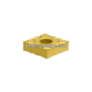
A bearing manufacturer was finish-turning AISI 52100 (62 HRC) bearing races on a CNC lathe. The initial parameters with a Korloy CBN insert (70% CBN content, TiAlN coated) were: Vc = 180 m/min, f = 0.08 mm/rev, ap = 0.15mm. Surface roughness was excellent (Ra 0.4 µm), but X-ray diffraction analysis revealed tensile residual stress of +350 MPa and a 12-micron white layer.
The engineering team adjusted the parameters to: Vc = 120 m/min (reduced to lower surface temperature), f = 0.10 mm/rev (slightly higher to increase mechanical compressive stress), ap = 0.20mm (above the minimum chip-formation threshold). A Korloy CBN insert with a 25-micron edge hone was used to create a slight burnishing effect at the cutting edge.
Results: surface roughness remained at Ra 0.5 µm (within spec), residual stress shifted to -280 MPa compressive (beneficial), and white layer was eliminated entirely. Bearing fatigue testing showed a 35% improvement in L10 life for the optimized parameters.
Preventing White Layer in Finish Machining
- Limit cutting speed: For hardened steels (50–65 HRC), keep Vc below 150 m/min for finish passes. For CBN tools, the sweet spot is typically 100–140 m/min.
- Use sharp or controlled-hone edges: Dull or heavily honed edges generate excessive friction and heat.
- Maintain adequate depth of cut: Never run finish passes below ap = 0.10mm. Below this threshold, the tool rubs rather than cuts, generating heat without material removal.
- Monitor tool wear rigorously: CBN tools can develop crater wear that concentrates heat at a small area. Replace at the first sign of surface degradation.
- Coolant considerations: For hard turning, dry machining with air blast is often preferred to avoid thermal shock. For grinding, copious coolant is essential.
Measuring Surface Integrity
Quality control for surface integrity requires specialized techniques beyond standard roughness measurement:
- X-ray diffraction (XRD): The standard method for measuring residual stress. Portable XRD units can measure directly on the machine bed for large components.
- Nital etch: A simple acid etch test that reveals white layer and thermal damage. Specified in many aerospace standards (AMS 2759, SAE AMS 2759/3).
- Microhardness profiling: Cross-section the part and measure hardness from the surface into the bulk at 10-micron intervals to detect work-hardening or softening.
- Barkhausen noise analysis: A non-destructive electromagnetic method that correlates with residual stress and microhardness in ferromagnetic materials.
Korloy CBN and Ceramic Inserts for Surface Integrity
Korloy manufactures a range of CBN (cubic boron nitride) and ceramic inserts specifically designed for finish hard turning where surface integrity is critical. Their CBN grades offer varying CBN content (50–90%) to balance wear resistance with edge toughness, and their edge preparation options—from sharp to controlled hone—allow process engineers to tune the burnishing effect for optimal compressive residual stress. Explore Korloy’s hard-turning insert range at hooguu.com.
Conclusion
Surface integrity is not a luxury specification—it is a functional requirement that directly affects the fatigue life, corrosion resistance, and reliability of machined components. By understanding the relationship between cutting parameters, tool condition, and subsurface metallurgy, process engineers can eliminate white layer, generate beneficial compressive residual stress, and deliver parts that perform reliably in service. The right tooling, combined with scientifically optimized parameters, makes the difference between a part that merely looks good and a part that is metallurgically sound.
Shop Related Products at HOOGUU