

Introduction to Tantalum and Niobium Machining
Tantalum and niobium (columbium) are closely related refractory metals frequently specified for chemical processing equipment, medical implants, superconducting components, aerospace hardware, and capacitor manufacturing. Both metals share Group 5 of the periodic table and exhibit similar machining challenges: high ductility, strong tendency to gall and weld to cutting tools, and sensitivity to interstitial contamination by oxygen, nitrogen, and carbon at elevated temperatures.
Tantalum (density 16.6 g/cm³, hardness 80–120 HV annealed) is among the densest commercially available metals. Its body-centered cubic structure provides excellent ductility — elongation to failure exceeds 30% in the fully annealed condition — but this same ductility produces long, stringy chips that wrap around tools and workpieces. Niobium (density 8.57 g/cm³, hardness 60–100 HV annealed) is lighter and somewhat softer, but equally prone to built-up edge (BUE) formation on cutting tools.
Tool Materials for Tantalum
Carbide Inserts (Primary Selection)
The best-performing carbide grades for tantalum fall in the ISO M10–M25 range (ANSI C2–C6), specifically those designed for sticky, gummy materials. Key requirements include:
- Sharp, polished cutting edges: Edge radius below 10 μm to shear rather than plow the soft material.
- Positive rake geometry: 20–30° effective rake reduces cutting forces and minimizes BUE adhesion.
- Low-friction coatings: TiCN + Al₂O₃ multilayer coatings (ISO PVD/CVD) reduce chip adhesion by 40–60% compared to uncoated carbide. CVD-coated grades such as KC5010, KC5025, and MP15A perform well.
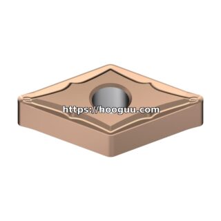
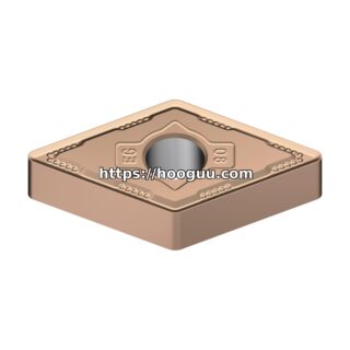
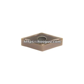
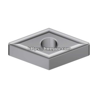
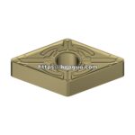
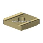
- Recommended inserts for turning: CCMT 09T304, DCMT 11T304, CNMG 120408 with polished top face.
- Recommended inserts for milling: APKT 1604PDER, LNEX 1506, SDXT 120408.
HSS Tools (Secondary Applications)
For low-volume jobs, form tools, and threading, M42 cobalt HSS (HRC 67–69) ground to razor-sharp edges provides acceptable results at lower speeds. HSS is particularly useful for boring bars, internal threading tools, and small-diameter drills where carbide would be too brittle.
Diamond Tools (Finishing Only)
Polycrystalline diamond (PCD) inserts deliver exceptional surface finish (8–16 μin Ra) on tantalum at moderate speeds. PCD is recommended only for continuous-cut finishing operations with clean workpiece surfaces. Avoid PCD for interrupted cuts due to edge chipping risk.
Cutting Parameters: Turning Tantalum
| Operation | Speed (SFM) | Speed (m/min) | Feed (IPR) | Feed (mm/rev) | Depth of Cut (in) | Depth (mm) |
|---|---|---|---|---|---|---|
| Rough Turning | 150–250 | 46–76 | 0.008–0.014 | 0.20–0.35 | 0.060–0.120 | 1.5–3.0 |
| Semi-Finish | 250–400 | 76–122 | 0.005–0.008 | 0.13–0.20 | 0.020–0.060 | 0.5–1.5 |
| Finish Turning | 400–600 | 122–183 | 0.002–0.005 | 0.05–0.13 | 0.005–0.020 | 0.13–0.50 |
Cutting Parameters: Turning Niobium
| Operation | Speed (SFM) | Speed (m/min) | Feed (IPR) | Feed (mm/rev) | Depth of Cut (in) | Depth (mm) |
|---|---|---|---|---|---|---|
| Rough Turning | 200–300 | 61–91 | 0.008–0.014 | 0.20–0.35 | 0.060–0.120 | 1.5–3.0 |
| Semi-Finish | 300–450 | 91–137 | 0.005–0.008 | 0.13–0.20 | 0.020–0.060 | 0.5–1.5 |
| Finish Turning | 450–700 | 137–213 | 0.002–0.005 | 0.05–0.13 | 0.005–0.020 | 0.13–0.50 |
Niobium machines approximately 20–30% faster than tantalum due to its lower hardness and density. Tool life targets: 30–60 minutes per edge for roughing, 60–120 minutes for finishing.
Cutting Parameters: Milling Tantalum and Niobium
| Operation | Speed (SFM) | Feed/Tooth (IPT) | Feed/Tooth (mm) | Axial DOC | Radial DOC |
|---|---|---|---|---|---|
| Face Milling – Ta | 200–350 | 0.005–0.009 | 0.13–0.23 | 0.080–0.150 in | 60–75% of Ø |
| Face Milling – Nb | 250–450 | 0.005–0.009 | 0.13–0.23 | 0.080–0.150 in | 60–75% of Ø |
| End Milling – Ta | 200–350 | 0.003–0.006 | 0.08–0.15 | 1.0× Ø | 10–20% of Ø |
| End Milling – Nb | 250–450 | 0.003–0.006 | 0.08–0.15 | 1.0× Ø | 10–20% of Ø |
| Slot Milling – Ta | 150–250 | 0.002–0.004 | 0.05–0.10 | 0.5× Ø | Full width |
Use carbide end mills with 2–3 flutes, 35–45° helix angle, and polished flutes. Climb milling direction reduces BUE formation on the entry cut.
Cutting Parameters: Drilling Tantalum and Niobium
| Operation | Speed (SFM) | Feed (IPR) | Notes |
|---|---|---|---|
| Drilling Ta (≤ 1/4″) | 60–90 | 0.002–0.003 | 135° split point, high helix, peck 1× Ø |
| Drilling Ta (1/4″ – 1/2″) | 70–110 | 0.003–0.005 | Peck cycle 2× Ø depth |
| Drilling Ta (> 1/2″) | 80–120 | 0.005–0.008 | Pilot hole then step drill |
| Drilling Nb (all sizes) | 90–150 | +30% over Ta values | Same geometry as Ta |
Critical Chip Control and BUE Management
The single greatest challenge when machining tantalum and niobium is managing built-up edge and chip welding. Strategies to mitigate BUE include:
- Never reduce feed mid-cut. Decreasing feed increases friction and heat, promoting BUE. Maintain or increase feed rate if BUE appears.
- Use sharp chip breakers. Positive-rake chip breaker geometries (e.g., Sandvik -MF, Kennametal MP) curl chips away from the cutting zone.
- Apply high-pressure coolant. 1,000–2,000 PSI through-tool coolant breaks chips and prevents rewelding. This is the single most effective BUE countermeasure.
- Polish insert rake faces. Mirror-finished rake faces reduce the nucleation sites for BUE formation.
- Maintain cutting speed above the BUE threshold. For tantalum, this threshold is typically above 200 SFM with coated carbide.
Coolant and Lubrication
Generous flood coolant is essential. Water-soluble synthetic or semi-synthetic coolant at 8–10% concentration is standard. Minimum flow: 5 GPM directed into the cut. For deep-hole drilling and tapping, through-tool coolant at 200–500 PSI is mandatory. Cutting oil (straight sulfurized or chlorinated) is acceptable for tapping and thread milling, where lubricity outweighs heat extraction needs.
Interstitial Contamination Prevention
Both tantalum and niobium absorb oxygen, nitrogen, and hydrogen at temperatures above 250°C, causing embrittlement in the heat-affected zone. Keep cutting temperatures controlled through adequate coolant delivery and avoid excessive dwell time at any point on the workpiece. If a machined surface shows blue or straw discoloration, contamination has occurred and the affected layer must be removed by grinding or chemical etching before further processing.
Surface Finish Expectations
As-machined tantalum and niobium surfaces achieve 32–63 μin Ra (0.8–1.6 μm) with standard finishing parameters. Electropolishing in a sulfuric-hydrofluoric acid bath produces mirror finishes of 4–8 μin Ra (0.1–0.2 μm) and removes the contaminated surface layer simultaneously. For medical-grade tantalum components, electropolishing is standard practice after machining.
Safety Notes
Tantalum powder and fine turnings are pyrophoric when dry — they can spontaneously ignite. Always keep chips wet with coolant or water during collection. Dispose of tantalum chips in covered containers with water immersion. Niobium chips are less pyrophoric but should still be handled as combustible metal waste. Both metals require Class D fire extinguishers in the machining area.
Summary
Successful machining of tantalum and niobium hinges on sharp, positive-rake coated carbide tools, generous flood or high-pressure coolant, and disciplined BUE management. Tantalum runs at 150–600 SFM depending on operation; niobium accommodates 20–30% higher speeds. Chip control, contamination prevention, and fire safety round out the essential practices for these reactive refractory metals.
Shop Related Products at HOOGUU