

Why Austenitic Stainless Steel Is Difficult to Turn
Austenitic stainless steels such as AISI 304 and 316 account for a large share of CNC turning work in the medical, food equipment, chemical and marine industries. Yet they remain one of the most frequently mis-machined material families in job shops. The difficulties come from four metallurgical characteristics that interact with the cutting process:
- High work-hardening tendency. 304 and 316 can work-harden from roughly 170 HB in the annealed condition to over 350 HB in a deformed surface layer only 0.1–0.3 mm deep. Any tool that rubs instead of cutting — because of excessive flank wear, too-light feed, or a honed edge on a finishing insert — creates a hardened skin that destroys the next cutting edge.
- Low thermal conductivity. At about 15 W/m·K, 304 conducts heat at roughly one-third the rate of 1045 carbon steel (around 50 W/m·K). Heat concentrates at the cutting edge instead of being carried away by the chip, raising edge temperatures and accelerating crater and flank wear.
- Tough, stringy chips. High ductility and elongation (40–60%) produce long continuous chips that wrap around the toolholder and workpiece unless the chip breaker and feed rate are chosen correctly.
- Built-up edge (BUE). At low cutting speeds the material pressure-welds to the cutting edge. BUE changes the effective geometry unpredictably, degrades surface finish, and chips the edge when it breaks off.
Successful stainless turning is therefore a system problem: geometry, grade, cutting parameters, coolant delivery and toolpath strategy must all work together. This guide covers each element with concrete numbers.
Insert Geometry and Chip Breaker Selection
Edge geometry: sharp and positive
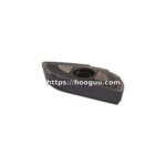
The single most important rule for austenitic stainless is to keep the cutting edge sharp and the rake positive. Negative-style double-sided inserts (CNMG, WNMG in heavy chip breakers) generate high cutting forces that push heat and work hardening into the surface. For the majority of stainless work, use:
- Finishing: positive inserts such as DCGT / CCGT / VCGT with a sharp, lightly honed edge (edge preparation around 0.01–0.02 mm), rake angle 15–20°, and a dedicated stainless finishing chip breaker (Walter FM4/FP5, Seco FF1, Sandvik -MF/-PF families).
- Medium machining: positive or lightly negative inserts with reinforced sharp edges — CCMT/DCMT positive styles or single-sided negative inserts in dedicated stainless breakers (Walter MM5/MP5, Seco MF4/MF5, Sandvik -MM/-PM).
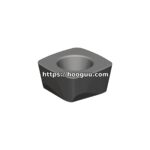
- Roughing: single-sided negative inserts with an open, high-positive breaker (Walter RP5/RP7, Seco MR7, Sandvik -PR/-MR). Reserve double-sided CNMG/WNMG for high-volume roughing where economy per edge dominates and machine rigidity is high.
Nose radius and entering angle
A common mistake is using an oversized nose radius for finishing. Large radii increase radial cutting force and promote vibration and work hardening. Practical guidance:
| Operation | Recommended nose radius | Reason |
|---|---|---|
| Finishing, Ra 0.8–1.6 µm | 0.2–0.4 mm | Lower radial force, less BUE, better chip thinning control |
| Medium turning | 0.4–0.8 mm | Balance of edge strength and force |
| Roughing, rigid setup | 0.8–1.2 mm | Feed per revolution must exceed ~30% of nose radius |
For the entering angle, 95° tools (SCLCR/DCLNR style) minimize radial pressure on slender parts. On rigid setups, 45° entering angle spreads wear over more edge length and improves tool life at the same feed.
Carbide Grade Selection: What the Leading Brands Offer
Stainless turning grades must combine a hard, heat-resistant coating with a tough, deformation-resistant substrate, because edge temperatures are high and the material’s toughness imposes mechanical shock. The modern answer from all major manufacturers is a fine-grained or gradient substrate with either PVD or advanced CVD coatings.
| Brand | Representative stainless turning grade | Coating type | Positioning |
|---|---|---|---|
| Walter | WMP20G / WSM21 (Tiger·tec Gold) | TiAlN-based PVD / multilayer CVD | Universal M-class; WMP20G emphasizes wear resistance at higher speed, WSM21 toughness for interrupted cuts |
| Seco | TM2000 / TM4000 (Duratomic) | Structured Al2O3 CVD with Ti(C,N) | TM2000 for continuous cuts and higher speed; TM4000 for toughness-demanding roughing |
| Sandvik | GC2220 / GC2025 (Inveio) | Unidirectional Al2O3 CVD over gradient substrate | GC2220 for stable conditions; GC2025 broad M-class workhorse with strong edge-line security |
| Iscar | IC907 / IC9250 (SUMO TEC) | PVD TiAlN / post-treated CVD | PVD sharpness for small parts and finishing; SUMO TEC CVD for productivity |
PVD vs CVD decision rule: choose PVD-coated sharp grades (Walter WSM series PVD variants, Iscar IC907/IC908, Kyocera PR1535) for finishing, small-diameter parts, low-power machines and any cut where edge sharpness matters more than thermal protection. Choose modern CVD grades (Seco TM2000, Sandvik GC2220, Walter WMP20G) for continuous roughing and medium turning at higher speed, where their thicker aluminum-oxide layer resists the intense heat generated in stainless.
Cutting Parameters: Starting Points That Actually Work
The tables below give practical starting parameters for coated carbide inserts on 304/316 in the annealed condition (~170 HB). Always verify against the insert supplier’s recommendations and adjust for rigidity, coolant and bar condition.
Cutting speed (Vc)
| Operation | PVD sharp grade | CVD M-class grade | Notes |
|---|---|---|---|
| Finishing | 120–180 m/min | 150–220 m/min | Never drop below ~90 m/min; BUE zone is roughly 30–80 m/min |
| Medium turning | 100–150 m/min | 130–190 m/min | Reduce 15–20% for 316 vs 304 |
| Roughing | 80–120 m/min | 110–160 m/min | Reduce 25–35% for interrupted cuts or scale/forged skin |
Two speed rules matter more than the absolute numbers. First, stay out of the built-up edge zone — if you see a ragged, torn surface finish, raise the speed rather than lower it. Second, once parameters are set, do not let the spindle RPM drop when turning toward center on facing passes; use constant surface speed (G96) so Vc stays stable and the edge stays ahead of the work-hardened layer.
Feed rate (f) and depth of cut (ap)
| Operation | Feed f (mm/rev) | Depth ap (mm) | Critical constraint |
|---|---|---|---|
| Finishing | 0.08–0.15 | 0.3–1.0 | Feed must exceed edge hone and work-hardened depth; never rub |
| Medium turning | 0.15–0.30 | 1.0–3.0 | Feed ≥ 30% of nose radius for proper chip breaker function |
| Roughing | 0.25–0.50 | 2.0–6.0 | Ap must exceed the work-hardened skin from the previous pass (typically ≥ 0.15 mm) |
The single most damaging habit in stainless turning is feed that is too light. A feed of 0.05 mm/rev at fine finishing depth lets the edge ride on the hardened skin instead of cutting beneath it, producing rapid notch wear at the depth-of-cut line. If surface finish requirements force a light feed, compensate with a small nose radius and a sharp PVD insert — not by slowing the spindle.
Specific cutting force reference
When sizing roughing passes against machine power, use specific cutting force kc1.1 ≈ 2450 N/mm² for 304/316 (compare ~1500–1800 N/mm² for medium carbon steel). A roughing pass of ap = 3 mm, f = 0.35 mm/rev, Vc = 140 m/min removes about 147 cm³/min and demands roughly 6 kW of spindle power plus machine reserve — a useful sanity check before quoting cycle times.
Coolant Strategy and Chip Control
Coolant: always on, always aimed
Stainless turning should run wet. High-pressure coolant is the preferred option where available:
- Conventional flood (0.5–1 MPa): acceptable for finishing and light medium work; ensure a generous flow directed precisely at the rake face contact zone.
- High-pressure coolant (7–15 MPa, precision nozzles): measurably improves chip breaking, edge temperature and tool life. Walter, Seco and Sandvik all report 30–50% tool-life gains in M-class materials with through-tool or precision overhead HPC, plus dramatically better chip evacuation in boring and grooving.
- Emulsion concentration: 8–12% for stainless; higher fat content improves lubricity and reduces BUE.
Breaking the chip
Long chips in stainless are not just inconvenient — a bird’s nest around the chuck destroys surface finish, trips spindle load alarms, and can snap an insert. If chips are not breaking:
- Increase feed first (most effective and free); the breaker is designed for a feed window.
- Reduce nose radius or switch to a sharper breaker style if feed cannot increase.
- Add high-pressure coolant aimed at the chip-curling zone.
- As a last resort, program a short retract (peck-style interruption) every 2–3 mm of turning length.
Common Failure Modes and Fixes
| Symptom | Likely cause | Corrective action |
|---|---|---|
| Notch wear at depth-of-cut line | Work-hardened skin, forged scale, rubbing feed | Vary ap between passes, increase feed, use tougher grade (e.g. Seco TM4000, Walter WSM21) |
| Built-up edge and poor finish | Vc in 30–80 m/min zone, dull edge | Raise Vc above 100 m/min, switch to sharper PVD insert, improve coolant lubricity |
| Rapid crater wear | Excessive speed/heat, wrong grade | Lower Vc 15–20%, move to Al2O3 CVD grade (TM2000, GC2220) |
| Chipping/fracture | Vibration, interrupted cut, too-brittle grade | Increase entering angle rigidity, larger nose radius, tougher grade, reduce feed at entry/exit |
| Chips wrapping | Feed below breaker window | Increase feed, sharper breaker, high-pressure coolant |
Practical Setup Checklist
- Confirm constant surface speed (G96) with an RPM clamp appropriate for the smallest diameter.
- Set first-pass ap at least 0.2 mm below the surface to cut under any work-hardened or scaled skin.
- Program feed to stay within the chip breaker’s window at the actual nose radius in use.
- Use the shortest tool overhang possible; for boring, keep L/D ≤ 4 with steel bars, ≤ 7 with carbide or damped bars.
- On slender shafts, support with a tailstock or steady rest and prefer 95° entering angle to cut radial force.
- Inspect the first insert at half the expected tool life to establish the actual wear pattern before committing to unattended running.
Summary
Turning 304 and 316 stainless profitably is a matter of respecting the material’s physics: keep edges sharp and positive, stay out of the built-up edge speed zone, feed aggressively enough to cut beneath the work-hardened layer, and use modern M-class grades — PVD for sharpness and finishing, advanced CVD (Walter Tiger·tec Gold, Seco Duratomic, Sandvik Inveio) for heated roughing. Combined with high-pressure coolant and disciplined chip-breaker selection, these practices routinely deliver 15–25 minutes of edge life per corner at 140–180 m/min in continuous cuts, with predictable, diagnosable wear instead of sudden edge failure.
Shop Related Products at HOOGUU