Introduction to Landing Gear Material Challenges
Landing gear components represent some of the most demanding machining applications in aerospace manufacturing. The combination of extreme cyclic loading, corrosion exposure, and stringent weight requirements forces engineers to select materials that are notoriously difficult to machine. Two alloys dominate this space: 300M steel (a modified 4340 with vanadium and higher silicon) and Ti-10V-2Fe-3Al (a near-beta titanium alloy). Both deliver exceptional strength-to-weight ratios but present unique challenges at the cutting edge.
At Hooguu, we supply carbide inserts and toolholders specifically engineered for these aerospace-grade materials. This guide covers real-world machining parameters, tooling selection, and process strategies used by Tier 1 and Tier 2 aerospace suppliers producing landing gear forgings.
300M Steel: Properties and Machining Characteristics
300M steel is a low-alloy, vacuum-melted steel with typical tensile strength exceeding 1,900 MPa (275 ksi) after heat treatment. Its composition includes 0.40% C, 1.65% Ni, 0.80% Cr, 0.40% Mo, and 1.60% Si, giving it deep hardenability and excellent fracture toughness.
In the normalized and tempered condition (before final heat treatment), 300M machines at approximately 300-340 HB. After quenching and tempering to full strength, hardness reaches 50-54 HRC, shifting it firmly into hard-turning territory. Most roughing is done in the pre-heat-treat state, while semi-finishing and finishing may be performed either pre- or post-heat-treat depending on the shop’s capability.
Rough Turning Parameters for 300M (Pre-Heat-Treat, 320 HB)
| Parameter | Roughing | Semi-Finishing | Finishing |
|---|---|---|---|
| Cutting Speed (Vc) | 120-160 m/min | 160-200 m/min | 200-260 m/min |
| Feed Rate (fn) | 0.30-0.45 mm/rev | 0.15-0.25 mm/rev | 0.08-0.15 mm/rev |
| Depth of Cut (ap) | 3.0-6.0 mm | 1.0-2.5 mm | 0.3-0.8 mm |
| Insert Grade | P25-P35 (MTCVD) | P15-P25 (MTCVD) | P10-P20 (CVD/PVD) |
| Coolant | Flood (emulsion 8-10%) | Flood or MQL | MQL or dry |
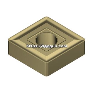
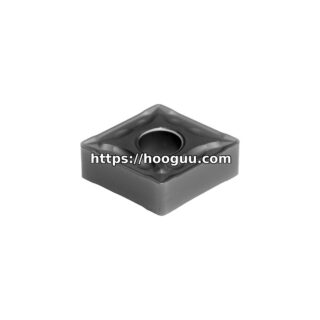
For roughing, a CNMG 120408 or CNMG 150612 insert with a medium-negative rake geometry and a tough MTCVD-coated grade like Sandvik 4325 or equivalent provides the best combination of edge toughness and wear resistance. The MTCVD coating offers superior crater wear resistance at the elevated temperatures generated when turning 300M at higher feeds.
Hard Turning 300M Post-Heat-Treat (50-54 HRC)
When finish-turning hardened 300M, CBN (cubic boron nitride) inserts are the standard choice. Recommended starting parameters:
- Cutting Speed: 120-180 m/min
- Feed Rate: 0.08-0.15 mm/rev
- Depth of Cut: 0.2-0.5 mm
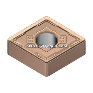
- Insert: CBN-tipped CNGA 120408, 65-70% CBN content, TiN or TiAlN binder
- Coolant: Dry or air blast (avoid thermal shock from flood coolant)
Achievable surface finish with CBN hard turning on 300M is typically Ra 0.4-0.8 um, sufficient for most bearing journal surfaces on main landing gear trunnions.
Ti-10V-2Fe-3Al: The Near-Beta Titanium Challenge
Ti-10V-2Fe-3Al (commonly called Ti-10-2-3) is a near-beta titanium alloy used extensively in Boeing 787 and Airbus A350 landing gear components. Its key advantage is a strength level comparable to 300M steel at roughly 60% of the weight. Typical tensile strength after solution treatment and aging is 1,200-1,310 MPa with hardness around 38-44 HRC.
Titanium alloys are poor thermal conductors. Only about 20-25% of heat generated during cutting is carried away by the chip; the remainder concentrates at the tool tip. This makes cutting speed the most critical parameter, as even modest increases can cause rapid tool degradation.
Machining Parameters for Ti-10-2-3
| Parameter | Roughing | Semi-Finishing | Finishing |
|---|---|---|---|
| Cutting Speed (Vc) | 30-50 m/min | 50-70 m/min | 70-100 m/min |
| Feed Rate (fn) | 0.20-0.35 mm/rev | 0.12-0.20 mm/rev | 0.08-0.12 mm/rev |
| Depth of Cut (ap) | 2.5-5.0 mm | 1.0-2.0 mm | 0.2-0.8 mm |
| Insert Grade | S15-S25 (PVD TiAlN) | S10-S20 (PVD) | S05-S15 (PVD) |
| Coolant | High-pressure flood (70 bar+) | High-pressure flood | High-pressure flood or MQL |
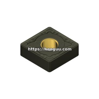
The ISO S-class grades are specifically formulated for titanium and heat-resistant alloys. A PVD TiAlN-coated insert provides the best balance of edge toughness and hot hardness. Avoid CVD-coated grades for titanium, as the CVD coating layer tends to micro-chip under the high cutting forces.
High-pressure coolant delivery at 70-150 bar through the toolholder is strongly recommended. This penetrates the chip-tool interface, improves chip evacuation, and dramatically extends tool life. Tests show tool life improvements of 200-400% when switching from standard flood (5-10 bar) to high-pressure (70+ bar) coolant on Ti-10-2-3.
Critical Tooling Considerations for Ti-10-2-3
Use a positive rake geometry with a sharp cutting edge (edge radius 15-25 um). Unlike steel turning where a honed or T-land edge improves toughness, titanium demands sharpness to minimize cutting forces and the associated heat generation. A sharp edge reduces cutting forces by 15-25% compared to a honed edge.
For the toolholder, a rigid capto C6 or C8 interface is preferred over conventional VDI or bolt-on systems. Deflection at the cutting edge causes chatter and poor surface finish, especially on the long, slender features common in landing gear inner cylinders.
Process Planning for Landing Gear Components
A typical main landing gear inner cylinder in 300M steel follows this process sequence:
- Forging: Near-net-shape forging with 3-5 mm machining allowance
- Normalize and Temper: Prepare for machining at 300-340 HB
- Rough Turning: Remove bulk material at high feed and depth of cut
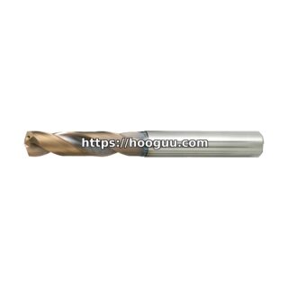
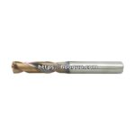
- Boring and Drilling: Internal features using anti-vibration boring bars
- Heat Treatment: Austenitize at 870 C, oil quench, temper at 260-315 C for target 50-54 HRC
- Semi-Finish Hard Turning: CBN inserts for journal diameters and seal grooves
- Finish Grinding: Final journal surfaces to Ra 0.2 um where required
- NADCAP-Approved NDT: Magnetic particle and ultrasonic inspection
When converting from grinding to hard turning, shops typically see a 50-70% reduction in cycle time and elimination of grinding swarf disposal costs. The key enabler is maintaining machine spindle accuracy below 2 um TIR and using hydrostatic or high-precision angular contact bearings.
Tool Life Expectations and Cost Optimization
For production planning purposes, typical tool life figures when machining landing gear components:
- 300M roughing (CNMG 150612, P35 MTCVD): 8-12 components per edge at Vc 140 m/min
- 300M hard turning (CBN CNGA 120408): 25-40 components per edge at Vc 150 m/min
- Ti-10-2-3 roughing (CNMG 120408, S20 PVD): 3-5 components per edge at Vc 40 m/min
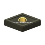
- Ti-10-2-3 finishing (DNMG 110404, S10 PVD): 8-15 components per edge at Vc 80 m/min
Tool cost per part is typically $45-$120 for 300M components and $80-$200 for Ti-10-2-3 components, reflecting the more aggressive wear environment in titanium. Investing in high-pressure coolant systems and premium-grade inserts typically yields a 20-35% net cost reduction through extended tool life and fewer unplanned tool changes.
Summary
Landing gear machining demands a disciplined approach to speed, feed, depth of cut, and tooling selection. Whether you are turning 300M steel at 1,900 MPa or Ti-10-2-3 at 40 m/min, success depends on matching the insert grade and geometry to the specific material condition and operation. At Hooguu, we stock a comprehensive range of ISO-standard carbide inserts, CBN-tipped tools, and high-pressure toolholders suited for aerospace landing gear production. Contact our technical team for application-specific recommendations.
Shop Related Products at HOOGUU