

Internal Threading on CNC Lathes: Insert Selection and Toolpath
Internal threading on CNC lathes is one of the most demanding turning operations. Unlike external threading, where chip evacuation and tool rigidity are manageable, internal threading forces the cutting tool to work inside a confined bore. This creates challenges related to tool deflection, chip flow, coolant delivery, and vibration. Selecting the right insert geometry, toolholder, and cutting parameters is critical for achieving accurate thread form, good surface finish, and acceptable tool life.
Insert Selection for Internal Threading
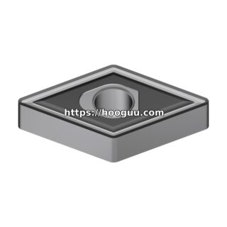
Internal threading inserts are typically smaller than their external counterparts due to the bore diameter constraint. The insert must clear the bore wall while maintaining sufficient strength. The key selection criteria include insert size, nose radius, coating, and chipbreaker geometry.
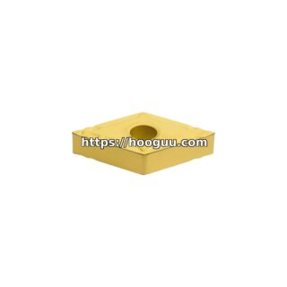
For bores between 16 mm and 40 mm diameter, use 11 mm or 16 mm insert sizes (ISO designation). The insert nose radius should match the thread root radius. For standard metric threads (M), a 0.2 mm to 0.4 mm nose radius covers most pitches from 1.0 mm to 3.0 mm. For UN threads, select the radius based on the specific thread form.
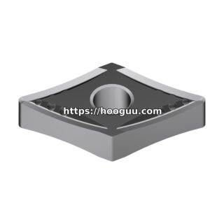
Carbide grades with PVD coatings (TiAlN, AlTiN) are preferred for internal threading because they maintain a sharp cutting edge while providing wear resistance. For steel workpieces (P-class materials), use grades in the P15 to P30 range. For stainless steel (M-class), select M15 to M25 grades with sharper geometry and higher hot hardness. For aluminum and non-ferrous materials, uncoated polished carbide or diamond-tipped inserts provide the best results.
Toolholder Considerations
The internal threading bar must have sufficient overhang to reach the full thread depth while minimizing deflection. A general rule: the overhang-to-diameter ratio should not exceed 4:1 for steel bars or 6:1 for carbide-reinforced (heavy metal) bars. When the ratio exceeds these limits, chatter becomes nearly unavoidable.
For deep internal threads requiring overhangs greater than 5 times bar diameter, consider anti-vibration boring bars with tuned mass damper systems. These bars contain an internal damping mechanism that absorbs vibrational energy, enabling stable cutting at overhang ratios up to 10:1 or even 14:1 in premium designs.
The bar clamping system matters significantly. Internal threading bars with coolant-through capability deliver pressurized coolant (typically 20 to 70 bar) directly to the cutting zone, which is essential for chip evacuation in blind hole threading applications. Minimum quantity lubrication (MQL) is generally insufficient for internal threading due to the enclosed cutting environment.
Cutting Parameters and Speeds
Internal threading cutting speeds are generally 20 to 30 percent lower than external threading speeds due to reduced rigidity and chip evacuation difficulties. Here are recommended starting parameters for common materials:
- Carbon steel (AISI 1045): Cutting speed 120 to 160 m/min, feed per revolution equals the thread pitch. For a 2.0 mm pitch thread, feed equals 2.0 mm/rev. Depth of cut per pass: 0.15 to 0.25 mm (radial).
- Stainless steel (AISI 304): Cutting speed 80 to 110 m/min. Use a modified flank infeed strategy to distribute wear. Depth per pass: 0.10 to 0.18 mm.
- Aluminum alloy (6061-T6): Cutting speed 200 to 300 m/min. Sharp uncoated inserts, depth per pass: 0.15 to 0.30 mm. Flood coolant or mist lubrication required to prevent built-up edge.
- Cast iron (GG25): Cutting speed 100 to 140 m/min. Dry cutting or air blast preferred. Depth per pass: 0.15 to 0.25 mm.
- Inconel 718: Cutting speed 25 to 40 m/min. Ceramic or whisker-reinforced carbide inserts. Depth per pass: 0.08 to 0.12 mm. High-pressure coolant mandatory (minimum 70 bar).
Toolpath Strategies
The infeed method dramatically affects tool life, surface finish, and cutting forces. The three primary toolpath strategies for CNC internal threading are:
1. Radial Infeed (Straight Plunge): The tool feeds perpendicular to the workpiece axis. Both flanks of the insert cut simultaneously. This method is simple but generates the highest cutting forces and is prone to chatter in internal applications. Use only for small pitches (under 1.5 mm) in rigid setups.
2. Flank Infeed (Single-Side): The tool feeds at an angle (typically 29 degrees or 29.5 degrees for 60-degree thread forms) so that only one flank of the insert does the cutting. This reduces cutting forces by approximately 30 to 40 percent compared to radial infeed. The leading flank angle should be set to half the thread angle minus 1 degree to avoid rubbing on the non-cutting flank.
3. Modified Flank Infeed (Alternating): The infeed alternates between the left and right flanks across successive passes. This distributes wear evenly across both cutting edges and is the preferred method for pitches above 2.0 mm. Many modern CNC controls (Fanuc, Siemens, Haas) offer this as a canned cycle option.
Number of Passes and Depth Distribution
The total thread depth for a standard metric thread is approximately 0.6134 times the pitch. For a 2.0 mm pitch, the full depth is about 1.227 mm. A typical pass schedule distributes depth progressively, with each successive pass taking a smaller cut as the cutting edge engagement increases:
- Pass 1: 0.30 mm radial depth
- Pass 2: 0.24 mm
- Pass 3: 0.18 mm
- Pass 4: 0.15 mm
- Pass 5: 0.12 mm
- Pass 6: 0.10 mm (finishing pass)
- Pass 7: 0.08 mm (spring pass for final size)
For harder materials (above 40 HRC), increase the number of passes by 40 to 50 percent with proportionally lighter cuts. Always include at least one spring pass at full depth to ensure the thread reaches the correct pitch diameter.
Chip Evacuation and Coolant Delivery
Chip evacuation is the single most critical factor in internal threading, especially for blind holes. Chips that accumulate in the bore can cause insert breakage, surface scoring, and dimensional errors. Internal coolant delivery through the boring bar at 30 to 70 bar pressure flushes chips away from the cutting zone. For through-holes, the natural chip flow direction (forward with right-hand threads) aids evacuation. For blind holes, consider programming a retract-and-clear cycle every 2 to 3 passes to allow chips to fall out of the bore.
Using inserts with positive rake geometry and polished chip surfaces reduces chip curl radius and helps produce short, manageable chips. Avoid negative rake geometry for internal threading unless machining hardened steels above 50 HRC.
Quality Control and Inspection
Internal threads are inspected using thread plug gauges (go/no-go) per ISO 1502 or ANSI/ASME B1.2. For production runs, in-process measurement using touch probes on the CNC lathe can verify pitch diameter within plus or minus 0.01 mm. Program a probing cycle after every 50 to 100 parts to detect tool wear trends and trigger automatic offset compensation. Surface roughness targets for internal threads are typically Ra 1.6 to 3.2 micrometers on the thread flanks.
Summary
Successful internal threading requires balancing insert selection, toolholder rigidity, cutting parameters, and toolpath strategy. Prioritize flank infeed methods to reduce cutting forces, maintain overhang ratios below 4:1 for standard bars, and ensure adequate coolant pressure for chip evacuation. With the correct setup, internal threads on CNC lathes can achieve consistent quality at production speeds comparable to external threading operations.
Shop Related Products at HOOGUU