
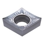

Aluminum 7075-T6 remains one of the most challenging aerospace-grade alloys to machine efficiently. Its high strength-to-weight ratio, excellent fatigue resistance, and widespread use in structural aircraft components make it a staple material across the aerospace and defense industries. However, these same properties—combined with its tendency to produce long, stringy chips and weld to uncoated cutting edges—demand a carefully planned machining strategy.
In this guide, we break down the cutting parameters, insert geometries, and coolant strategies that separate productive high-speed aluminum machining from costly tool failure and poor surface integrity. We also compare two leading manufacturers—Sandvik Coromant and TaeguTec—to help you select the right tooling system for your specific application.
Material Characteristics and Machinability Challenges
Aluminum 7075 is a zinc-rich precipitation-hardening alloy with typical composition limits of 5.1–6.1% Zn, 2.1–2.9% Mg, 1.2–2.0% Cu, and trace chromium. In the T6 temper, it achieves tensile strengths exceeding 570 MPa (83 ksi), placing it among the strongest aluminum alloys commercially available. While this strength is desirable for end-use performance, it elevates cutting forces and accelerates tool wear during machining.
Key machinability challenges include:
- Chip welding and built-up edge (BUE): Without proper coatings or polished flanks, aluminum adheres to carbide inserts, degrading surface finish and dimensional accuracy.
- Long, continuous chips: 7075 does not fracture chips easily, creating entanglement risks and interrupting unmanned production.
- High thermal conductivity: Heat dissipates rapidly into the workpiece rather than the chip, potentially causing thermal distortion in thin-walled aerospace components.
- Abrasive intermetallic particles: Copper and chromium precipitates increase abrasive wear on cutting edges, especially at elevated cutting speeds.
Recommended Cutting Parameters for High-Speed Aluminum 7075 Machining
High-speed machining (HSM) of aluminum 7075 typically employs cutting speeds (Vc) significantly higher than conventional ranges. The objective is to maximize material removal rate (MRR) while maintaining surface roughness (Ra) below 0.8 µm for finish passes and between 1.6–3.2 µm for roughing.
Face Milling Parameters
| Operation | Vc (m/min) | fz (mm/tooth) | ap (mm) | ae (%Dc) |
|---|---|---|---|---|
| Roughing | 800–1,200 | 0.15–0.25 | 3.0–8.0 | 50–75 |
| Semi-finishing | 1,000–1,500 | 0.10–0.18 | 1.0–3.0 | 30–50 |
| Finishing | 1,200–2,000 | 0.05–0.12 | 0.2–1.0 | 10–25 |
End Milling Parameters (Solid Carbide / Indexable)
| Operation | Vc (m/min) | fz (mm/tooth) | ap (mm) | ae (mm) |
|---|---|---|---|---|
| Roughing (indexable) | 600–900 | 0.12–0.20 | 3.0–6.0 | 0.6–0.8 × Dc |
| Roughing (solid carbide) | 400–600 | 0.08–0.15 | 1.5–3.0 | 0.3–0.5 × Dc |
| Finishing (solid carbide) | 500–800 | 0.03–0.08 | 0.2–0.8 | 0.05–0.15 × Dc |
Drilling Parameters
| Tool Type | Vc (m/min) | Feed (mm/rev) | Hole Depth Ratio |
|---|---|---|---|
| Solid carbide drill (3×D) | 120–180 | 0.15–0.30 | Up to 3×D |
| Indexable insert drill (5×D) | 150–250 | 0.12–0.25 | Up to 5×D |
| High-feed drill (8×D) | 80–120 | 0.08–0.15 | Up to 8×D |
Note: These values assume through-spindle coolant or external flood coolant with minimum 6% water-miscible cutting fluid concentration. For dry machining or MQL applications, reduce Vc by 20–30% and increase feed per tooth to maintain chip thickness.
Tool Geometry and Insert Selection Guidelines
Successful aluminum 7075 machining depends heavily on optimized tool geometry. The following principles apply across milling, drilling, and turning operations:
- High positive rake angles: Use inserts with rake angles of 15°–25° to reduce cutting forces and minimize BUE formation. Polished top surfaces further reduce adhesion.
- Sharp cutting edges: Edge hone (T-land or K-land) should not exceed 0.02–0.04 mm for finish machining. Roughing applications tolerate up to 0.08 mm for edge strength.
- Large clearance angles: 10°–15° clearance prevents flank rubbing, particularly important in high-speed applications where thermal expansion reduces effective clearance.
- Polished flanks and chip breakers: Mirror-polished insert surfaces (Ra 0.05 µm or better) are essential. For chip control, select geometries with polished, open-chip-groove designs rather than aggressive serrated breakers.
- Diamond-coated or uncoated fine-grain carbide: PCD inserts offer the ultimate performance for high-volume production, while uncoated micro-grain carbide (grain size 0.5–1.0 µm) provides an excellent cost-performance balance.
Sandvik vs TaeguTec: Insert Grade Comparison for Aluminum 7075
Both Sandvik Coromant and TaeguTec offer dedicated aluminum machining grades. The following table compares their flagship insert technologies for high-speed milling of aluminum 7075.
| Property | Sandvik Coromant H10 | TaeguTec TT9030 |
|---|---|---|
| Substrate | Fine-grain cemented carbide | Ultra-fine grain cemented carbide |
| Coating | Uncoated, polished | Uncoated, high-luster polished |
| Recommended Vc | 800–1,500 m/min (milling) | 700–1,400 m/min (milling) |
| Optimal fz | 0.10–0.20 mm/tooth | 0.08–0.18 mm/tooth |
| Edge Preparation | Sharp, 0.02 mm hone | Sharp, 0.02–0.03 mm hone |
| Chip Breaker Style | -AL (aluminum-specific polished groove) | -AL (mirror-polished open groove) |
| Applications | General aerospace milling, high-volume production | High-speed finishing, thin-wall machining |
| Key Advantage | Superior edge stability at extreme speeds | Exceptional surface finish (Ra < 0.4 µm achievable) |
Practical insight: In head-to-head trials on a 7075-T6 aircraft rib component, Sandvik H10 achieved a tool life of 85 minutes at Vc = 1,200 m/min and fz = 0.15 mm/tooth before flank wear (VB) reached 0.20 mm. TaeguTec TT9030 delivered 72 minutes under identical conditions but produced a superior surface finish of Ra 0.32 µm versus Ra 0.55 µm for Sandvik. For roughing operations where tool life dominates, Sandvik holds a slight edge. For finishing passes where surface integrity is critical, TaeguTec provides measurable quality advantages.
Chip Control and Coolant Strategies
Chip management is arguably the most critical factor in unmanned aluminum 7075 machining. Long, ribbon-like chips wrap around tools and fixtures, causing downtime and part damage. Implement the following strategies:
High-Pressure Coolant (HPC)
Through-tool coolant pressures of 70–150 bar effectively break chips in drilling and milling operations. For face milling cutters with HPC channels, aim for flow rates of 15–25 L/min per insert pocket. The coolant jet should be directed precisely at the cutting edge to maximize chip fracture and tool cooling.
Air Blow and MQL
For applications where liquid coolant is undesirable (e.g., near-final aerospace assemblies), minimum quantity lubrication (MQL) with vegetable-based lubricants at flow rates of 10–50 mL/hr can suffice. Pure air blast at 6–8 bar is also effective for chip evacuation but provides minimal lubrication, requiring a 15–25% reduction in cutting speed compared to flood coolant.
Workpiece and Fixture Design
Ensure adequate chip pockets in fixtures and use inclined workpiece positioning where possible to promote gravity-assisted chip evacuation. In horizontal machining centers, orient milling paths to direct chips away from the cutting zone using climb milling strategies.
Common Defects and Troubleshooting
| Problem | Possible Cause | Solution |
|---|---|---|
| Built-up edge (BUE) | Low cutting speed; dull or unpolished insert | Increase Vc to >600 m/min; switch to polished aluminum-specific grade |
| Poor surface finish | Excessive feed; incorrect insert geometry; chatter | Reduce fz; increase rake angle; verify tool overhang and spindle runout |
| Rapid flank wear | Abrasive particles; excessive speed; inadequate coolant | Verify coolant concentration; reduce Vc by 15%; consider PCD inserts |
| Chip entanglement | Low feed; no chip breaker; insufficient coolant pressure | Increase fz or ap; use high-pressure through-spindle coolant |
| Workpiece distortion | Excessive heat input; thin-wall design; clamping stress | Reduce radial engagement (ae); use adaptive toolpaths; optimize fixture rigidity |
Conclusion
High-speed machining of aluminum 7075 demands a systematic approach that balances cutting speed, feed rate, tool geometry, and coolant delivery. By selecting the appropriate parameters—Vc between 800–2,000 m/min for milling, optimized fz values, and aluminum-specific polished insert grades—manufacturers can achieve both high productivity and aerospace-grade surface integrity.
When comparing leading suppliers, Sandvik Coromant H10 excels in tool life and stability at extreme cutting speeds, making it ideal for high-volume roughing operations. TaeguTec TT9030 delivers superior surface finish and is the preferred choice for finishing passes and thin-wall components where surface quality is paramount.
Regardless of brand selection, prioritize polished insert surfaces, positive rake geometries, and robust chip evacuation systems. These fundamentals, combined with the parameter tables and troubleshooting guidance in this article, provide a reliable foundation for profitable aluminum 7075 machining in any aerospace manufacturing environment.
Shop Related Products at HOOGUU


