

The Crankshaft: Where Volume Meets Precision
The automotive crankshaft is one of the highest-volume precision-machined components in the world, with global production exceeding 80 million units per year. Whether forged from micro-alloyed steel or cast from nodular iron, the crankshaft demands a combination of high metal removal rates and tight geometric tolerances that push turning technology to its limits.
Modern crankshaft turning lines must hold journal diameter tolerances of 0.02-0.05 mm, surface finish of Ra 0.8-1.6 um on main journals and pin journals, and cylindricity below 0.015 mm. All of this must be achieved at cycle times measured in minutes, not hours.
Material: Forged Steel Grades
The most common forged crankshaft steels are:
- 38MnVS6 (1.1303): A micro-alloyed medium-carbon steel with vanadium. Hardness after controlled cooling from forging: 250-290 HB. Tensile strength: 800-950 MPa. This is the European standard grade for passenger car crankshafts.
- C70S6 / 70MnVS4: Higher-carbon fracture-splitting grades used for connecting rods and some crankshafts. Hardness: 270-310 HB.
- 42CrMo4 (1.7225 / AISI 4140): Used for heavy-duty and diesel engine crankshafts. Quenched and tempered to 280-330 HB before machining, with tensile strength of 900-1,100 MPa.
The vanadium micro-alloyed steels present a unique challenge: their hardness is relatively moderate, but the vanadium carbides create localized abrasive wear on cutting edges. This means insert wear is not uniform and tends to concentrate on the flank face near the depth-of-cut line.
External Turning: Main and Pin Journals
Crankshaft turning is typically performed on dedicated CNC crankshaft lathes (Heller, Boehringer, or Hitachi Seiki) with driven tool turrets and part-specific fixturing. The operation sequence is:
Step 1: Rough Turning Main Journals
| Parameter | Value |
|---|---|
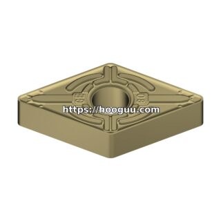
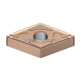
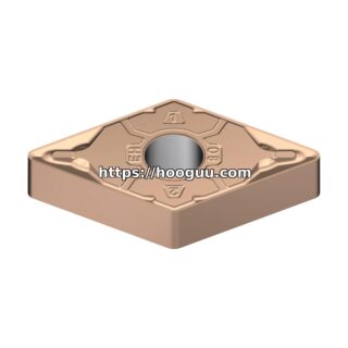
| Insert | CNMG 190612 (ISO), CVD TiCN/Al2O3 coated |
| Grade | P25-P35 (e.g., Sandvik 4325, Kennametal KCP25B) |
| Cutting Speed (Vc) | 180-240 m/min |
| Feed Rate (fn) | 0.40-0.60 mm/rev |
| Depth of Cut (ap) | 4.0-8.0 mm |
| Coolant | Flood emulsion, 8-10% concentration |
| Metal Removal Rate | 400-1,150 cm3/min |
The large CNMG 190612 insert provides a strong cutting edge with a 1.2 mm nose radius and sufficient chip-breaking capacity for the high feed rates. At these parameters, tool life is typically 80-150 components per edge, which is essential for untended production.
Step 2: Semi-Finish and Finish Turning
| Parameter | Semi-Finish | Finish |
|---|---|---|
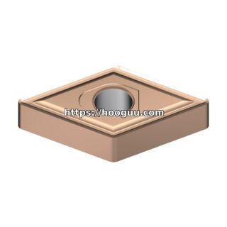
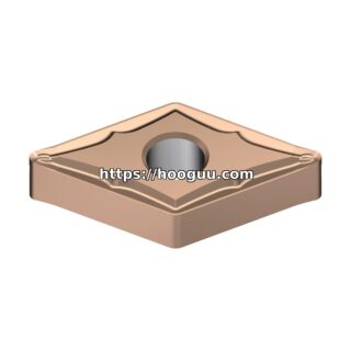
| Insert | CNMG 120408 | DNMG 150608 or CNMG 120408 |
| Grade | P15-P25 | P10-P15 |
| Vc | 220-280 m/min | 280-350 m/min |
| fn | 0.20-0.35 mm/rev | 0.10-0.18 mm/rev |
| ap | 1.0-2.5 mm | 0.3-0.8 mm |
| Surface Finish | Ra 1.6-3.2 um | Ra 0.8-1.6 um |
For the finish pass, a wiper insert (such as DNMG 150608 with wiper geometry) allows higher feed rates while maintaining surface finish. A wiper flat on the insert’s trailing edge burnishes the surface, enabling feeds of 0.18-0.25 mm/rev while still achieving Ra 0.8-1.2 um. This directly reduces cycle time.
Internal Turning: Oil Hole Drilling and Boring
Crankshafts feature oil passages drilled through the main and pin journals. These are typically 5-8 mm diameter cross-drilled holes that intersect at specific angles. While drilling is the primary operation, some designs require counter-boring or internal chamfering using boring bars.
For cross-drilling:
- Tool: Solid carbide drill, 6 mm diameter, 12x diameter depth, TiAlN coated
- Cutting Speed: 120-160 m/min (6,370-8,490 RPM)
- Feed Rate: 0.08-0.12 mm/rev
- Coolant: Through-tool at 30-50 bar
- Holes per tool: 800-1,500 holes
Chip Control: The Production Killer
In high-volume crankshaft production, chip control is often the limiting factor for productivity. Long, stringy chips from the continuous cuts on journals can wrap around the workpiece, tangle in the toolholder, and trigger machine stoppages. This is especially problematic with ductile micro-alloyed steels.
The solution lies in proper chip-breaker selection:
- Roughing: Use an insert with an aggressive chip-breaker geometry designed for medium-to-heavy chip sections. The Sandvik -MR or Kennametal -MP chip breaker, for example, produces tight C-shaped chips at feeds of 0.40-0.60 mm/rev.
- Finishing: A lighter chip-breaker geometry (-MF or -FP) is needed for the thinner chips produced at lower feeds. These geometries curl and break chips at feeds as low as 0.10 mm/rev.
Poor chip control in crankshaft turning accounts for an estimated 15-25% of unplanned downtime on automated production lines. Investing time in chip-breaker optimization yields immediate ROI.
Fillet Rolling and Turning Integration
Many crankshaft designs require fillet rolling on the journal-to-web transitions to induce compressive residual stresses and improve fatigue life. The turning operation must leave a precise fillet profile that the rolling tool can engage. Typical fillet radii are 3-5 mm, and the turned surface in the fillet must be free of feed marks that could act as stress risers.
For fillet turning, use a form insert or a tool with a matching nose radius. Feed rates must be reduced to 0.06-0.10 mm/rev in the fillet zone to minimize feed marks. The resulting surface should be Ra 1.6 um or better before rolling.
Tool Life Management in High-Volume Production
In a typical automotive crankshaft line producing 200,000+ units per year, tool change logistics are critical. Here is a representative tool life management strategy:
| Operation | Tool | Parts per Edge | Edges per Insert | Total Parts |
|---|---|---|---|---|
| Rough main journals | CNMG 190612 | 80-150 | 4 | 320-600 |
| Rough pin journals | CNMG 190612 | 60-120 | 4 | 240-480 |
| Finish main journals | CNMG 120408 | 200-400 | 4 | 800-1,600 |
| Finish pin journals | DNMG 150608 | 150-300 | 4 | 600-1,200 |
| Cross drilling | 6mm carbide drill | 800-1,500 | 1 | 800-1,500 |
Most modern CNC crankshaft lathes feature tool monitoring systems that track cutting force or acoustic emission to detect insert wear and trigger tool changes before quality limits are breached. This enables lights-out production with minimal scrap risk.
Conclusion
Crankshaft machining demands high-productivity tooling that delivers consistent tool life, reliable chip control, and excellent surface finish across hundreds of parts. The right combination of insert grade, geometry, and cutting parameters determines whether a line meets its OEE (Overall Equipment Effectiveness) targets or bleeds money on unplanned downtime. Hooguu supplies the full range of ISO turning inserts, chip-breaker geometries, and toolholders needed for crankshaft production lines worldwide.
Shop Related Products at HOOGUU