

Why Brake Rotors Demand High-Speed Machining
Automotive brake rotors are among the highest-volume cast iron machining applications in the world, with global annual production exceeding 500 million units. The material is relatively soft (grey cast iron at 180-230 HB), but the sheer volume demands extreme cycle time reduction. Every second saved in the machining cycle translates to thousands of dollars in annual savings across a production line.
Brake rotors also demand good surface finish for brake pad bedding, tight parallelism between the two friction faces (0.01-0.02 mm), and minimal disc thickness variation (DTV) below 0.005 mm. These geometric requirements, combined with the need for speed, make brake rotor turning a unique application.
Material: Grey Cast Iron Grades
Brake rotors are cast from grey iron, typically to specifications such as:
- GJL-200 (EN 1561) / SAE J431 Class G3000: Tensile strength 200 MPa minimum, hardness 180-220 HB. Used for standard passenger car rotors.
- GJL-250 / SAE G3500: Tensile strength 250 MPa minimum, hardness 200-240 HB. Used for heavier vehicles and performance applications. Higher carbon equivalent gives better damping but increased abrasiveness.
- High-carbon grey iron (3.6-4.0% C): Used in premium and aftermarket rotors for improved thermal conductivity and damping. Hardness 190-230 HB.
Grey iron is classified as an ISO K-class workpiece material. Its short, brittle chips make chip control easy, but the graphite flakes within the matrix are abrasive to cutting edges. The key to successful machining is selecting grades that resist abrasive flank wear while maintaining enough toughness to handle the interrupted cuts common in rotor geometry.
Turning Operations: A Two-Side Story
A typical brake rotor machining line consists of:
- OP10: First side machining: rough and finish turn outboard friction face, bore center hole, turn hat section
- OP20: Second side machining: rough and finish turn inboard friction face, turn OD
- OP30: Drilling and tapping of mounting holes, balance correction
Rough and Finish Turning Parameters
| Parameter | Roughing (Outboard Face) | Finishing (Both Faces) |
|---|---|---|
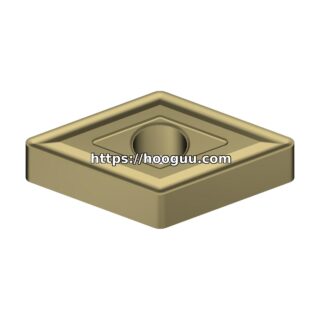
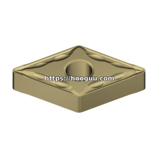
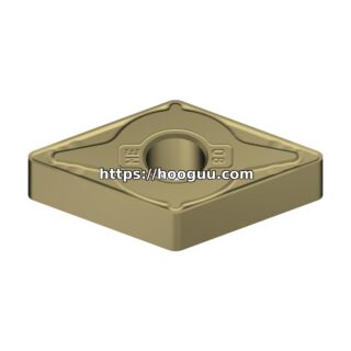
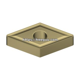
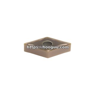
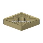
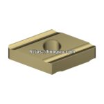
| Insert | CNMG 120408 or SNMG 120408 | CCMT 09T308 or DNMG 150608 (wiper) |
| Grade | K15-K25 (CVD TiCN/Al2O3) | K10-K20 (CVD or PVD) |
| Cutting Speed (Vc) | 300-500 m/min | 500-800 m/min |
| Feed Rate (fn) | 0.30-0.50 mm/rev | 0.15-0.35 mm/rev |
| Depth of Cut (ap) | 2.0-4.0 mm | 0.3-1.0 mm |
| Coolant | Dry or air blast (preferred) | Dry or MQL |
| Surface Finish | Ra 3.2-6.3 um | Ra 0.8-2.5 um |
The most striking aspect of brake rotor turning is the cutting speed. At 500-800 m/min for finishing, brake rotor turning runs at speeds that would destroy most tooling in other applications. Grey iron’s brittle fracture behavior and low cutting forces at these speeds allow CVD-coated inserts to operate far beyond their normal speed range.
Why Dry Machining Dominates
The vast majority of modern brake rotor lines run dry or with minimum quantity lubrication (MQL). The reasons are compelling:
- Chip Evacuation: Grey iron produces short, broken chips (type 6-9 on the ISO chip classification). These chips fall away by gravity and don’t need coolant flushing. Flood coolant can actually cause chip recirculation, damaging the machined surface.
- Thermal Stability: At 500+ m/min cutting speeds, flood coolant creates thermal cycling that accelerates thermal cracking in the insert. Dry machining maintains a stable temperature at the cutting edge.
- Environmental and Cost: Eliminating coolant saves $0.50-$1.50 per part in coolant purchase, filtration, disposal, and environmental compliance. At 500,000 parts per year, that represents $250,000-$750,000 in annual savings.
- Graphite Dust Management: Dry machining does produce graphite dust. This is managed with extraction systems rated for particulate removal at 99.9%+ efficiency with HEPA filtration.
Wiper Inserts: The Productivity Multiplier
Wiper geometry inserts have revolutionized brake rotor finishing. A wiper flat on the insert’s trailing edge burnishes the surface, allowing higher feeds while maintaining finish. Consider the comparison:
| Parameter | Standard Insert | Wiper Insert | Improvement |
|---|---|---|---|
| Feed Rate | 0.15 mm/rev | 0.30 mm/rev | +100% |
| Surface Finish (Ra) | 1.2 um | 1.0 um | Better |
| Cycle Time (per face) | 8.5 seconds | 4.3 seconds | -49% |
For a typical brake rotor with a 200 mm friction face diameter and 0.30 mm/rev feed at 600 m/min, the finishing pass takes only 3.5-5 seconds per face. Total machining cycle time (both sides, rough and finish) for a standard passenger car rotor is 35-60 seconds.
Managing Disc Thickness Variation (DTV)
DTV is the thickness difference between any two points on the rotor measured at the same radius. Excessive DTV causes brake judder (pulsation felt in the brake pedal). The machining process must hold DTV below 0.005 mm to meet OEM specifications.
Factors that influence DTV in turning:
- Spindle Accuracy: Runout at the workholding face must be below 0.003 mm TIR
- Clamping Distortion: Hydraulic or pneumatic chucks must apply uniform clamping force. Distortion from uneven clamping relaxes after unclamping, creating DTV. Use diaphragm chucks or compensating jaw systems.
- Thermal Growth: The rotor heats up during machining. If the first face is machined cold and the second face is machined hot, differential thermal expansion causes parallelism error. Solution: machine both faces simultaneously using opposed twin-tool turrets, or implement a consistent thermal cycle.
- Tool Wear Compensation: As inserts wear, the cutting edge position changes. Automatic tool compensation triggered by in-process gauging is essential on high-volume lines.
Insert Grade Recommendations for Grey Iron
The K-class ISO application range covers grey iron. Specific grade selection depends on the operation:
- Roughing (intermittent cuts, e.g., slotted rotors): K20-K30 with a tough substrate and CVD TiCN/Al2O3 coating. The tougher substrate resists chipping at slot interruptions.
- Roughing (continuous cuts): K15-K20 with CVD coating. Higher wear resistance is prioritized since chipping risk is lower.
- Finishing: K05-K15 with either CVD or PVD coating. PVD TiAlN provides a sharper edge for better surface finish. CVD Al2O3 provides maximum abrasive wear resistance.
Tool Life and Production Economics
Typical tool life in high-volume brake rotor production:
- Rough turning (CNMG 120408, K20 CVD): 500-1,000 parts per edge at Vc 350 m/min, 4 edges per insert
- Finish turning (DNMG 150608 wiper, K10 CVD): 800-2,000 parts per edge at Vc 600 m/min, 4 edges per insert
At a production rate of 2,000 rotors per day, rough inserts last 1-2 days and finish inserts last 2-4 days. Tool cost per part is typically $0.05-$0.15, making brake rotor turning one of the most cost-efficient machining operations in automotive production.
Conclusion
Brake rotor machining exemplifies high-speed, high-volume production where every parameter matters. From dry cutting at 800 m/min to wiper inserts that halve cycle times, the technology continues to evolve. Hooguu supplies K-class carbide inserts in standard and wiper geometries, optimized for grey iron turning at the speeds and feeds that modern brake rotor lines demand. Contact us for application support and volume pricing on brake rotor tooling programs.
Shop Related Products at HOOGUU