
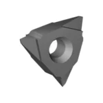

Thread Turning Insert Grades and Geometry: The Two Variables That Decide Thread Quality
Thread turning looks deceptively simple. The machine feeds the tool at exactly the thread pitch, the insert plunges a triangular form into a rotating bar, and a thread appears. In practice, most threading problems on a lathe — torn crests, chipped tips, pitch drift, chatter on coarse pitches, and threads that gauge tight at the go/no-go station — trace back to two decisions made long before the cycle starts: which grade cuts the material and which profile geometry defines the form.
This guide compares two of the most widely used thread turning systems in general engineering: the Iscar IC908 grade in the 16ER / 11IR insert platform and the Vargus (Vardex) VM7 grade in the same ISO insert format. Both are PVD-coated carbide systems covering the ISO P, M, K and S envelope, both index on a single central screw, and both are stocked in the 16 mm external and 11 mm internal inscribed-circle sizes. The real differences show up in coating architecture, edge preparation, profile coverage, and behaviour when cutting stainless steel and superalloys.
1. What Actually Determines Thread Turning Success
A thread is a geometry transfer, not a free-form cut. Three requirements have to be met simultaneously:
- Form accuracy. The insert profile must reproduce the specified flank angle, crest width, root radius and thread height within the tolerance class (for example 6g external or 6H internal for ISO metric threads).
- Chip control at small depth of cut. Thread turning removes a long, thin, V-shaped chip at depths of cut that shrink pass by pass. If the chip curls back into the groove, it is re-cut, work-hardens, and destroys the edge.
- Edge stability on a weak tool. A threading insert has a small cross-section, a sharp 60° included angle and often a long overhang. Vibration is the default failure mode, not the exception.
Every parameter choice in this article — speed, number of passes, infeed direction, coolant pressure — exists to serve one of those three requirements.
2. Insert Platform and Nomenclature
Both brands follow the ISO/ANSI thread turning insert naming convention, which is what makes them interchangeable on the same holder. Decoding the code is the first step in any selection decision:
| Designation | Meaning | Typical pitch range | Application |
|---|---|---|---|
| 11IR | 11 mm inscribed circle, internal, right-hand | 0.5–1.5 mm | Small-bore internal threads, M6–M20 |
| 16IR | 16 mm inscribed circle, internal, right-hand | 1.0–3.0 mm | General internal threads, M10–M36 |
| 16ER | 16 mm inscribed circle, external, right-hand | 0.5–3.0 mm | General external threads, M4–M36 |
| 22ER / 27ER | Larger external platforms | 2.5–6.0 mm | Coarse pitches, large-diameter shafts |
Two further letters matter. Full-profile inserts are ground to one exact pitch and cut the complete thread form, including crest truncation and root radius. Partial-profile inserts (typically designated AG60, or 55° for Whitworth) cut only the flank angle and cover a pitch range.
Both Iscar and Vargus offer the same split, and both use a screw-on clamping design with a torx key. Indexing accuracy across the pocket is therefore a genuine differentiator: any play between insert and pocket becomes a flank-angle error on the part, which is why holders from either brand should be treated as a matched system rather than a universal accessory.
3. Grade Comparison: Iscar IC908 vs Vargus VM7
IC908 is Iscar’s workhorse PVD grade for threading and grooving, and it is the grade most job shops specify when they buy 16ER inserts from that brand. VM7 is Vargus’ universal PVD thread turning grade, positioned to cover steel, stainless and cast iron with a single insert. Their published positioning is nearly identical; their construction is not.
| Property | Iscar IC908 | Vargus VM7 |
|---|---|---|
| Coating type | PVD TiAlN, single-layer architecture | PVD TiAlN, multilayer architecture |
| Coating thickness (typical) | 2–4 µm | 2–4 µm |
| Coating microhardness | ~3,000–3,300 HV | ~3,000 HV |
| Substrate | Submicron carbide, ~10% Co | Micrograin carbide, corrosion-resistant binder |
| Edge preparation | Light honing, sharp but stabilised | Sharp ground edge with micro-hone |
| ISO coverage | P, M, K, S (moderate), limited N | P, M, K, S, limited N |
| Oxidation limit (guide) | ~900 °C | ~900 °C |
| Coating colour | Gold-bronze | Gold-bronze |
| Typical Vc, ISO P | 120–180 m/min | 110–170 m/min |
| Typical Vc, ISO M | 60–100 m/min | 60–95 m/min |
Values above are typical catalogue ranges and field-proven starting points; always confirm against the current manufacturer data sheet before locking a program.
Where IC908 has the advantage
IC908’s single-layer TiAlN and slightly tougher substrate give it a measurable edge in interrupted threading — keyways, cross-holes, and threads that open into a shoulder where the insert exits under load. The grade tolerates the micro-impact of a discontinuous cut better than a harder, more wear-resistant coating, and its honed edge resists the small chipping that turns into a torn crest two passes later. In medium-carbon steel at 150–180 m/min, IC908 is the more forgiving choice for shops running mixed lots on older lathes with less rigid tooling.
Where VM7 has the advantage
VM7’s multilayer coating is built for adhesion resistance, which matters most in austenitic stainless and duplex grades. The 304/316 family work-hardens instantly under a dull edge, and the resulting built-up edge lifts the coating and smears the flank. VM7’s smoother, multilayer top layer reduces that tendency and holds its sharpness longer at the 60–90 m/min window where stainless threading actually runs. Vargus also offers VKX for hardened work up to roughly 55 HRC and VM3 for general-purpose and non-ferrous work, so a shop already standardised on the Vardex holder system can cover the full range without changing platforms.
The honest verdict
At ISO P, the two grades are close enough that holder rigidity and infeed strategy dominate the result. At ISO M, VM7 is the safer default. At ISO S — Inconel 718, 17-4PH, titanium — neither grade is a magic solution: both require low speed, high-pressure coolant and a modified flank infeed, and both will fail early if the overhang is excessive.
4. Full Profile vs Partial Profile: The Decision Most Shops Get Wrong
| Feature | Full profile (e.g. 16ER150ISO) | Partial profile (e.g. 16ER AG60) |
|---|---|---|
| Pitch coverage | One pitch per insert | 0.5–3.0 mm with one insert |
| Crest and root form | Fully formed, including root radius | Flanks only; crest truncated, root radius not controlled |
| Tolerance class capability | 6g / 6H achievable | Dependent on operator-controlled thread height |
| Tool inventory | One SKU per pitch | One SKU per angle family |
| Best application | Production, gauged threads, safety-critical parts | Job shop, repair work, unknown or mixed pitches |
| Thread height control | Built into the insert | Must be set by X-offset and verified by gauge |
The trade-off is inventory versus compliance. A full-profile insert guarantees the root radius and crest width that a 6g external thread requires, because the geometry is ground into the carbide. A partial-profile insert asks the programmer to calculate thread height (0.6134 × pitch for a sharp-V external thread, 0.5413 × pitch for internal) and to stop the infeed at the right X value. That is entirely workable for repair and single-piece work, but it is a source of variation that production shops should not accept on a gauged thread.
For coarse pitches above 3 mm, move to the 22ER or 27ER platform. The larger inscribed circle provides more supporting carbide behind the tip, which is the single most effective fix for chatter on coarse threads.
5. Cutting Parameters: Speed, Passes and Depth of Cut
Thread turning is a low-speed, multi-pass operation. The single most common programming error is running a threading insert at the same surface speed as a turning insert, which converts a 12-pass thread into a two-pass failure.
5.1 Surface speed by ISO material group
| ISO | Material example | Vc, Iscar IC908 | Vc, Vargus VM7 | Notes |
|---|---|---|---|---|
| P | C45 / 1045, 4140 | 120–180 m/min | 110–170 m/min | Flood coolant; reduce 20% on coarse pitches |
| M | 304, 316L, duplex | 60–100 m/min | 60–95 m/min | Modified flank infeed mandatory |
| K | GGG40, GGG60 | 100–150 m/min | 100–140 m/min | Dry or MQL often acceptable |
| N | 6061-T6, 7075 | 250–400 m/min* | 250–400 m/min* | *Uncoated or PCD, sharp edge |
| S | Inconel 718, Ti-6Al-4V | 25–40 m/min | 25–35 m/min | High-pressure coolant, one-pass-per-depth discipline |
| H | 45–52 HRC | 40–70 m/min | 40–60 m/min | CBN above 50 HRC |
For aluminium, TiAlN is the wrong coating: it is chemically compatible with the workpiece and tends to pick up. Use an uncoated, polished, sharp-edged insert, or a PCD-tipped threading insert for high-volume work.
5.2 Number of passes and thread height
| Pitch (mm) | Thread height, external (mm) | Passes, ISO P | Passes, ISO M |
|---|---|---|---|
| 0.50 | 0.307 | 6 | 7 |
| 0.75 | 0.460 | 7 | 8 |
| 1.00 | 0.613 | 7 | 9 |
| 1.25 | 0.767 | 8 | 10 |
| 1.50 | 0.920 | 9 | 11 |
| 2.00 | 1.227 | 10 | 13 |
| 2.50 | 1.534 | 12 | 15 |
| 3.00 | 1.840 | 14 | 17 |
Thread height is calculated as h = 0.6134 × P for a sharp-V external thread and h = 0.5413 × P for an internal thread before crest truncation. For a 1.5 mm pitch, that is 0.920 mm of radial infeed distributed over roughly nine passes.
Depth of cut per pass should not be uniform. A practical distribution for a 1.5 mm pitch external thread in steel is 0.30 mm on the first pass, then 0.20, 0.15, 0.12, 0.09, 0.06, 0.04, 0.03, 0.02 mm. The first passes remove most of the material while the edge is strongest and the chip is widest; the last passes refine the flanks. On stainless, cap the first pass at 0.25 mm and add one finishing pass rather than increasing the finishing depth.
6. Infeed Strategy: Radial, Flank and Modified Flank
Three infeed methods are used in thread turning, and the choice affects chip thickness distribution far more than most operators expect:
- Radial infeed (cross infeed). Both flanks cut equally. Simple, but produces a wide, thin chip that is hard to evacuate and generates high radial force. Acceptable for fine pitches (below 1.0 mm) and free-cutting brass.
- Flank infeed. The tool feeds along one flank at half the included angle (30° for a 60° thread). The active edge cuts with a controlled chip thickness and the trailing flank burnishes. Best general-purpose method for steel.
- Modified flank infeed. Flank infeed with a small radial component (typically 2–5° offset). Reduces flank wear on the leading edge while keeping chip control. This is the standard recommendation for stainless, duplex and superalloys.
On a Fanuc-style control, G76 two-line cycle supports these strategies directly through the infeed angle parameter (P). Setting P to 30000 for a 60° thread gives flank infeed; P at 60000 or 0 gives radial. For internal threads, remember that the infeed direction must be mirrored relative to the bore axis, and that a left-hand insert is needed for a right-hand internal thread when cutting toward the chuck.
7. Coolant, Chip Evacuation and Work Hardening
In external threading, chip evacuation is rarely the limit; in internal threading it usually is. A V-shaped chip that stays in a 10 mm bore is re-cut on the next pass, and re-cutting austenitic stainless raises surface hardness from roughly 200 HV to 350–400 HV in the affected layer. Once that happens, the remaining passes cut hard-machined material with a sharp, brittle edge — the classic path to a chipped tip.
Practical measures that consistently work:
- Use through-tool or directed high-pressure coolant (30–70 bar) on internal threads, aimed to flush chips out of the bore rather than into it.
- Increase coolant concentration for stainless; oil-based or high-EP water-soluble coolant improves flank finish and reduces built-up edge.
- Program a short retract-and-flush dwell between roughing and finishing passes on threads deeper than 2× diameter.
- Avoid dwell at the thread end on stainless — a stationary tool on a rotating workpiece work-hardens the root.
8. Thread Turning vs Thread Milling: When to Switch Process
| Criterion | Thread turning | Thread milling |
|---|---|---|
| Cycle time, small parts | Fast, one tool, multiple passes | Slower, helical interpolation |
| Large or non-rotating parts | Requires lathe or large chuck | Any machining centre, part stays clamped |
| Thread close to a shoulder | Needs relief groove | Full thread to the bottom, no relief |
| Tool breakage risk | Higher on small bores | Lower, multi-flute cutter, easier to retract |
| Typical Vc, ISO P | 120–180 m/min | 100–200 m/min |
| Typical Vc, ISO S | 25–40 m/min | 40–70 m/min |
| Best fit | High-volume shafts, standard threads | Large parts, difficult materials, blind holes |
Thread milling is not a replacement for thread turning; it is a fallback for geometry and material problems that turning cannot solve. Where both are possible, turning wins on cycle time, and milling wins on risk.
9. Application Decision Matrix
| Application | Recommended insert | Grade | Infeed |
|---|---|---|---|
| M8–M16 external, carbon steel, production | 16ER full profile, exact pitch | IC908 or VM7 | Flank, 30° |
| M20+ internal, 304/316 | 16IR full profile | VM7 | Modified flank |
| Repair threads, mixed pitch | 16ER / 16IR AG60 | IC908 | Flank, thread height gauged |
| Inconel 718, 17-4PH | 16ER full profile, sharp edge | VM7 or IC908 | Modified flank, high-pressure coolant |
| 45–52 HRC shafts | 16ER full profile | VKX or CBN-tipped | Flank, reduced first pass |
| Aluminium, high volume | 16ER full profile, polished | Uncoated / PCD | Radial, high speed |
| Coarse pitch above 3 mm | 22ER / 27ER | IC908 or VM7 | Flank, rigid holder |
10. Failure Modes and Their Real Causes
- Torn or rough crest. Usually built-up edge from speed too high for stainless, or a dull edge from too many passes. Reduce Vc by 15–20%, not the number of passes.
- Chipped tip on the first pass. Insert not seated in the pocket, or first-pass depth too aggressive for the pitch. Clean the pocket and cap the first pass at 0.30 mm.
- Chatter on coarse threads. Overhang above 1.5× shank height, or a 16 mm platform used where a 22ER belongs. Fix the holder before changing the grade.
- Thread gauges tight but mikes measure correct. Flank angle error from a worn or misindexed insert, or a partial-profile insert stopped at the wrong X. Check the insert pocket and verify thread height with a thread measuring wire.
- Pitch drift over a long thread. Feed and spindle synchronisation error, not a tool problem. Verify the G76 pitch value and the encoder feedback before blaming the insert.
Key Takeaways
- IC908 and VM7 are both capable universal PVD grades; the difference is edge toughness (IC908, better on interrupted cuts) versus adhesion resistance (VM7, better on stainless and duplex).
- Choose full-profile inserts for gauged, production threads and partial-profile AG60 inserts only for repair and mixed-pitch work.
- Run thread turning at 120–180 m/min in carbon steel and 60–95 m/min in stainless — not at turning speeds.
- Distribute infeed over 9 passes for a 1.5 mm pitch, with a heavy first pass and light finishing passes.
- Use modified flank infeed and high-pressure coolant on any material that work-hardens; the chip, not the coating, is usually what breaks the tool.
Thread turning rewards discipline more than it rewards premium grades. A correctly seated IC908 or VM7 insert, a rigid holder, the right number of passes and a directed coolant stream will out-cut an expensive grade running a radial infeed at turning speed every time.
Shop Related Products at HOOGUU