
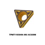
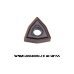
Turning productivity is rarely decided by the insert grade alone. In practice, the combination of substrate, coating and chipbreaker geometry determines whether an insert survives a roughing pass at 0.4 mm/rev or fails by crater wear after forty minutes. Korloy’s turning system is built around exactly this pairing: a small family of coated grades (PC5300, PC9030 and PC8110 being the most widely used) matched to a set of chipbreaker geometries designated FA, SA, MA, MM, HM and SM. Understanding how those two halves interact makes insert selection far more predictable than catalog browsing.
This guide breaks down the Korloy turning grade and chipbreaker architecture, gives reference cutting data for common workpiece materials, and compares the system against equivalent Sandvik, Iscar, Seco and Tungaloy solutions so that a shop can translate existing programs rather than re-learn turning from scratch.
Why Grade and Chipbreaker Must Be Selected Together
An insert is a thermal and mechanical system. The coating controls how much heat reaches the substrate and how much abrasion the rake face can absorb; the chipbreaker controls how the chip is bent, how contact length is distributed, and how much cutting force is transferred into the tool holder. A hard, wear-resistant grade paired with an open roughing groove will chip at the edge; a tough grade paired with a tight finishing groove will built-up-edge and smear the surface.
The practical rule is simple: select the grade from the workpiece material and the chipbreaker from the depth of cut and feed rate. Korloy’s catalog follows this logic, which is why the same PC5300 substrate appears in finishing, medium and heavy geometries with different edge preparations.
Korloy Turning Grade Portfolio
The three grades below cover the majority of general turning work in steel, stainless steel and cast iron. Values are typical catalog ranges and should be treated as starting points, not absolutes.
| Grade | Coating architecture | Substrate | ISO application range | Typical Vc, steel (m/min) | Best suited to |
|---|---|---|---|---|---|
| PC5300 | CVD multilayer TiCN + Al2O3, total thickness approx. 8–12 µm | Cobalt-enriched gradient carbide, 10–11 % Co at the surface | P15–P25, K20–K30, M20 | 200–280 (C45 / 1045) | Continuous and lightly interrupted turning of carbon and alloy steel; general purpose production |
| PC9030 | CVD TiCN base with thicker Al2O3 top layer for thermal insulation | Tougher carbide, higher Co, fine grain | P25–P35, K25–K35 | 170–250 | Forgings with scale, interrupted cuts, heavy roughing, older or less rigid machines |
| PC8110 | PVD TiAlN, monolayer, approx. 3–5 µm, high oxidation resistance | Fine-grain carbide with controlled Co content | M15–M30, S15–S25, P20 | 140–220 (304 / 316) | Stainless steel, duplex and super-duplex, heat-resistant alloys, built-up-edge prone materials |
The distinction between PC5300 and PC9030 is thermal, not chemical. Both use an alumina top layer, but PC9030 carries a thicker oxide layer and a tougher substrate, which raises the maximum temperature the edge can tolerate during a interrupted cut. In a stable continuous operation PC5300 will usually outlast it because the thinner coating keeps the edge sharper and generates less friction. Using PC9030 for finishing is a common and expensive mistake: the edge radius and the thicker coating both raise cutting forces at small depths of cut.
PC8110 exists because austenitic stainless steel destroys alumina coatings through a combination of adhesion and chemical reaction with the cobalt binder. A PVD TiAlN layer with a smoother, more oxidation-resistant surface reduces welding and keeps the notch wear at the depth-of-cut line under control, provided coolant delivery is adequate.
Korloy Chipbreaker Geometries
Korloy designates turning chipbreakers by two letters that describe the application window rather than a single number. The table below summarises the behaviour of the most common geometries. Groove width, rake angle and edge hone values are reference figures for a standard CNMG or WNMG insert and vary slightly by insert shape.
| Chipbreaker | Application | Feed range fn (mm/rev) | Depth of cut ap (mm) | Rake angle | Edge hone | Notes |
|---|---|---|---|---|---|---|
| FA | Finishing | 0.05–0.15 | 0.3–1.5 | approx. 20° positive | 0.02–0.03 mm | Narrow groove, low cutting force, best surface finish; avoid below 0.04 mm/rev |
| SA | Semi-finishing | 0.10–0.25 | 0.8–3.0 | approx. 15° | 0.03–0.04 mm | Good compromise for mixed finishing and light roughing on the same tool |
| MA | Medium machining | 0.20–0.45 | 1.5–5.0 | approx. 10° | 0.04–0.05 mm | Widest working range; standard choice for general CNC turning |
| HM | Heavy roughing | 0.35–0.80 | 4.0–8.0 | approx. 6° | 0.06–0.08 mm | Reinforced edge for forging scale and interruptions; higher power demand |
| SM | Stainless / M group | 0.15–0.35 | 1.0–4.0 | approx. 14° | 0.03–0.05 mm | Polished rake face, anti-welding geometry, pairs with PC8110 |
| MM | Medium, M group | 0.20–0.40 | 2.0–5.0 | approx. 12° | 0.04–0.05 mm | Stronger edge than SM, for interrupted stainless cuts |
Two limits matter more than the nominal feed range. The minimum feed is set by chip thickness: below roughly one third of the groove width the chip stops curling and turns into a string, which is the usual cause of sudden edge breakage. The maximum depth of cut is set by chip flow direction; exceeding it pushes the chip against the groove wall and produces a burr at the trailing edge. When a program cannot satisfy both, change the chipbreaker before increasing power.
Reference Cutting Data by Workpiece Material
The following matrix combines grade and chipbreaker selection with starting values for speed and feed. It assumes a rigid CNC lathe, through-tool or high-pressure coolant where noted, and a tool holder with sufficient overhang stiffness.
| Workpiece | Hardness | Grade | Chipbreaker | Vc (m/min) | fn (mm/rev) | ap (mm) | Coolant |
|---|---|---|---|---|---|---|---|
| Carbon steel C45 / 1045 | 180–220 HB | PC5300 | MA | 240 | 0.30 | 2.5 | Flood, 6–8 bar |
| Alloy steel 4140 | 28–32 HRC | PC5300 | SA | 210 | 0.20 | 1.8 | Flood |
| Alloy steel 4140, forged with scale | 30–35 HRC | PC9030 | HM | 170 | 0.45 | 4.5 | Flood, high volume |
| Stainless 304 | 180 HB | PC8110 | SM | 160 | 0.22 | 2.0 | High pressure, 15–20 bar |
| Stainless 316L | 180–200 HB | PC8110 | SM | 140 | 0.18 | 1.5 | High pressure preferred |
| Cast iron GGG40 | 190–220 HB | PC5300 | MA | 200 | 0.28 | 3.0 | Dry or air blast |
| Tool steel 1.2344 (H13) | 42–48 HRC | PC8110 | MM | 120 | 0.15 | 1.2 | Flood |
Reduce Vc by 15–20 % for the first tool on a new program and bring it up to the table value only after checking flank wear at the ten-minute mark. Increase feed before increasing speed if the chip is breaking correctly but tool life is short; a 20 % feed increase at constant speed generally costs less life than a 20 % speed increase because the heat input per unit of chip volume stays closer to equilibrium.
Competitive Comparison: Equivalent Grades Across Brands
Shops rarely run a single brand, so the useful question is which competitor insert occupies the same application window. The table below maps Korloy grades to close equivalents and notes the practical differences that show up on the shop floor.
| Application window | Korloy | Sandvik | Iscar | Seco | Tungaloy | Practical difference |
|---|---|---|---|---|---|---|
| Steel, continuous, general purpose | PC5300 | GC4325 | IC8250 | TP2501 | T9125 | GC4325 and T9125 use a thicker alumina layer and tolerate slightly higher speeds; IC8250 has the sharpest edge of the group |
| Steel, interrupted / scaled | PC9030 | GC4335 | IC8350 | TP3501 | T9215 | PC9030 and GC4335 behave similarly on scale; IC8350 is more tolerant of vibration but wears faster in clean cuts |
| Stainless and heat-resistant alloys | PC8110 | GC1115 | IC807 / IC908 | CP500 | AH725 | PC8110 and GC1115 are close on 304; IC908 holds up better under interrupted stainless cuts |
| Heavy roughing, large depth | PC9030 + HM | GC4335 + M5 | IC8350 + M3 | TP3501 + M3 | T9215 + GH | Korloy HM groove is wider than the M5, so it breaks chips at lower feed in large depths |
| Finishing, low Ra requirement | PC5300 + FA | GC4325 + M3 | IC8250 + F3P | TP2501 + M1 | T9125 + NS | FA and M3 are comparable; both require fn above 0.05 mm/rev to avoid stringy chips |
The mapping is a starting point rather than an equivalence claim. Coatings differ in thickness and pre-treatment, and edge hones vary by a few hundredths of a millimetre, which is enough to change behavior at 0.05 mm/rev. Whenever an insert is substituted across brands, adjust feed first and speed second.
Chip Control in Practice
Chip form is the fastest diagnostic available on a lathe. Six common patterns and their usual causes:
- Long, stringy chips — feed too low for the groove width, or depth of cut below the chipbreaker’s design range. Raise fn by 20–30 % before changing anything else.
- Chips that curl but do not break — cutting speed too low for the material, so the chip is too ductile. Raise Vc by 10–15 % or apply more coolant pressure.
- Fan or cone shaped chips — depth of cut too shallow relative to the nose radius. Increase ap to at least 0.6 times the radius.
- Blue or discolored chips with crater wear — speed too high for the grade, or coolant missing the cutting zone. Check the grade’s ISO window.
- Chipping at the depth-of-cut line — notch wear from a work-hardened surface, common on stainless and forged steel. Reduce Vc by 15 %, or use a tougher grade such as PC9030.
- Built-up edge and poor surface finish — adhesion in stainless or low-carbon steel. Switch from an alumina coating to PC8110 and raise the surface speed.
For stainless steel the most common error is running the same feed as steel but at a much lower speed, which produces work hardening ahead of the edge and rapid notch wear. Keep the feed at or above 0.15 mm/rev, keep the tool engaged, and avoid dwelling at the start of a pass.
Edge Preparation and Tool Life
Korloy applies a T-land or hone to every coated turning insert, and the specification matters when inserts are reconditioned or when a shop regrinds its own tools. A hone of 0.02–0.03 mm on FA inserts is designed to be removed by the first few minutes of cutting; regrinding a used FA insert restores the groove but destroys the hone, which changes the effective chipbreaker and usually produces chipping. For that reason, reground finishing inserts should be run at 80–90 % of the catalog speed.
Tool life expectations for a correctly matched grade and chipbreaker in alloy steel are typically 15–20 minutes at the table values above, with flank wear of 0.25–0.35 mm as the limit. Crater wear on the rake face is usually the first failure mode at high speed, and notch wear at the depth-of-cut line is the first failure mode in stainless and forged work. Monitoring both, rather than only flank wear, gives a much earlier warning of an unsuitable pairing.
Selection Checklist
- Identify the material group first (P, M, K, S), then the grade, then the chipbreaker.
- Match the chipbreaker’s minimum feed to the programmed feed, not to the maximum the machine can deliver.
- Keep ap above 0.5 times the nose radius; below that, chip control becomes geometry-limited.
- Use PC5300 for stable steel turning and PC9030 only where interruptions or scale demand it.
- Use PC8110 with SM or MM for stainless, and never run it dry in a deep groove.
- Increase feed before speed when tool life is short; reduce speed first when chipping appears.
- Record the grade, chipbreaker, Vc, fn, ap and observed tool life for every job — the best insert database is the one built from your own machines.
Conclusion
Korloy’s turning range is not a long list of interchangeable inserts. PC5300, PC9030 and PC8110 each own a specific thermal and chemical territory, and the FA, SA, MA, MM, HM and SM chipbreakers define the feed and depth window in which that grade can actually work. Selecting the two together, and adjusting feed before speed when conditions change, produces predictable chip control and tool life across steel, stainless and cast iron. The comparison with Sandvik, Iscar, Seco and Tungaloy is useful mainly as a translation table; the physics of chip bending and coating wear is the same regardless of the label on the box.
Shop Related Products at HOOGUU