
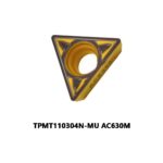
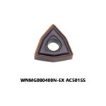
Two shops can run the same 80 mm face mill on the same 4140 block at the same spindle speed and get completely different tool life. The difference is usually not the grade or the coating — it is the geometry. Lead angle, rake angle, helix angle and corner radius are the four numbers that decide how thick the chip actually is, where the cutting force is directed, and how much heat reaches the insert edge. This reference explains how each geometry variable changes the cutting parameters you program, and gives working tables for ISO P, M, K, N, S and H materials.
Lead Angle: The Number That Rewrites Your Feed Rate
The lead angle (also called entry angle or approach angle, κ) is measured between the main cutting edge and the workpiece surface. It is the single most misunderstood value in milling, because it changes the actual chip thickness without changing the feed per tooth you type into the control.
The relationship is simple:
hm = fz × sin κ
where hm is the mean chip thickness, fz the feed per tooth, and κ the lead angle. At a 90° lead angle the chip is as thick as the feed per tooth. At 45° it is only 71% of that. At a 10° lead angle it collapses to 17%, so a cutter that looks like it is being fed aggressively is actually rubbing rather than cutting.
This effect is called chip thinning, and it has two consequences:
- Low lead angles let you raise the table feed substantially while keeping the same chip load — good for metal removal rate.
- If you do not raise the feed, the edge rubs, work-hardens the surface and wears rapidly — the classic failure mode of high-feed cutters run at conventional feeds.
To convert a target chip thickness into a programmed feed per tooth:
fz,program = htarget / sin κ
Table 1 — Lead angle, chip thinning factor and typical depth of cut
| Lead angle | Chip thinning factor (sin κ) | Typical ap | Chip thickness at fz = 0.20 mm | Force direction | Best application |
|---|---|---|---|---|---|
| 90° | 1.000 | 0.5–3 mm | 0.200 mm | Radial (toward spindle) | Square shoulders, thin walls, weak fixtures |
| 75° | 0.966 | 1–4 mm | 0.193 mm | Mainly radial | Shoulder milling with moderate ap |
| 60° | 0.866 | 2–6 mm | 0.173 mm | Mixed | General roughing, ramping |
| 45° | 0.707 | 3–8 mm | 0.141 mm | Balanced radial/axial | Face milling, high removal rate |
| 30° | 0.500 | 4–10 mm | 0.100 mm | Mainly axial | Heavy roughing on rigid machines |
| 10–15° | 0.174–0.259 | 6–12 mm | 0.035–0.052 mm | Axial (toward column) | High-feed milling, shallow ap per pass |
Three practical rules follow from this table:
- Low lead angles push force axially. A 10° high-feed cutter loads the spindle axially and is gentle on thin walls, but demands a rigid machine and a well-supported workpiece.
- 90° cutters push force radially. They are the safer choice for long overhangs and thin-walled parts, but they cannot take a deep ap because the insert is presented square to the cut.
- 45° is the compromise. The force vector splits roughly evenly, the insert can be double-sided and economical, and ap can reach 6–8 mm with a 80 mm diameter body.
Rake Angle: Where the Cutting Energy Goes
Rake angle controls the shear plane. A positive rake lifts the chip away from the workpiece and lowers cutting force, at the cost of a weaker edge. A negative rake puts the edge in compression, which is ideal for interrupted cuts and cast iron, but raises the force and the heat generated at the edge.
For indexable inserts, the effective rake is the sum of the insert’s own rake and the body’s axial and radial rake. Most double-sided face mill bodies use −6° axial and −6° radial rake with inserts that add a positive chipbreaker geometry, giving a net neutral-to-positive cut.
Table 2 — Recommended rake by ISO material group
| ISO group | Effective rake | Edge preparation | Reason |
|---|---|---|---|
| P — steel | +6° to +12° | Honing 0.03–0.05 mm, T-land on roughing | Balances chip flow with edge strength for interrupted cuts |
| M — stainless | +8° to +15° | Sharp or light hone 0.02 mm | Reduces work hardening and built-up edge |
| K — cast iron | −4° to +6° | Heavy hone 0.05–0.08 mm | Compressive edge survives scale and interruptions |
| N — aluminium | +15° to +25° | Polished, sharp | Low force, prevents built-up edge, enables high speed |
| S — superalloys | +10° to +15° | Sharp with controlled hone | Minimises subsurface deformation and notch wear |
| H — hardened steel | −5° to −10° with chamfer | Chamfer 0.1–0.2 mm × 20° | Edge strength under very high specific cutting force |
A common mistake is buying a high-positive aluminium-style insert and running it in steel. The edge is too sharp for the interrupted load, and it chips within a few passes. Conversely, a strong negative insert run in 6082 aluminium simply rubs, builds up edge and produces a poor surface.
Helix Angle and Axial Force
In end milling and shoulder milling, helix angle determines how smoothly the cutter engages and how much axial force is generated. Higher helix gives a longer shear cut, quieter operation and better surface finish, but it also pulls the tool along the spindle axis — a problem for long reach tools and thin floors.
Table 3 — Helix angle selection
| Helix angle | Axial force | Typical use | Notes |
|---|---|---|---|
| 0–10° | Very low | Hard materials, thin floors, slotting of composites | Harsh entry, needs rigid setup |
| 30° | Low–medium | General steel and stainless milling | Good balance for roughing |
| 38–45° | Medium–high | Aluminium, high removal rates, finishing | Quiet cut, excellent finish, high MRR |
| 50–60° | High | Aluminium aerospace, dynamic milling | Only with short, rigid tools |
With variable-pitch (differential) cutters, the helix angles alternate, which breaks the harmonic that causes chatter at specific spindle speeds. On a 12 mm end mill in 316 stainless at 40 mm overhang, a differential-pitch cutter often allows 20–30% higher ap before the first chatter lobe appears.
Corner Radius and the Feed Limit
Corner radius (rε) sets the maximum chip load the insert can survive at the leading corner and the minimum ap that still cuts rather than rubs. A rough guide for roughing is fz ≈ 0.6–0.8 × rε; for finishing, 0.2–0.4 × rε.
Table 4 — Corner radius versus feed and application
| rε | Roughing fz | Finishing fz | Minimum ap | Application |
|---|---|---|---|---|
| 0.4 mm | 0.10–0.20 mm | 0.05–0.12 mm | 0.3 mm | Small parts, thin ribs, finishing |
| 0.8 mm | 0.20–0.40 mm | 0.10–0.25 mm | 0.6 mm | General purpose, the default choice |
| 1.2 mm | 0.30–0.60 mm | 0.15–0.35 mm | 1.0 mm | Medium roughing, moulds |
| 1.6–2.0 mm | 0.40–0.90 mm | 0.25–0.50 mm | 1.5 mm | Heavy roughing, large cavities |
Wiper inserts are the exception: a wiper flat on the corner allows finishing feeds 2–3× higher than the table above at the same Ra, because the flat removes the cusp left by the radius. They must be set 0.02–0.05 mm lower than the working inserts and only used where the surface is uninterrupted.
Worked Example: From Geometry to Program Values
Take an 80 mm 45° face mill, 6 teeth, roughing 4140 at 280 HB, target mean chip thickness 0.18 mm, ap 4 mm, ae 60 mm, coolant flood.
- Programmed feed per tooth: fz = 0.18 / sin 45° = 0.18 / 0.707 = 0.255 mm.
- Cutting speed for coated carbide in P at 280 HB: Vc = 230 m/min.
- Spindle speed: n = 1000 × Vc / (π × D) = 1000 × 230 / (π × 80) = 915 rpm.
- Table feed: vf = fz × z × n = 0.255 × 6 × 915 = 1,400 mm/min.
- Metal removal rate: Q = ap × ae × vf / 1000 = 4 × 60 × 1400 / 1000 = 336 cm³/min.
Now run the same target with a 90° square-shoulder cutter, 6 teeth, same diameter and speed:
- fz = 0.18 / sin 90° = 0.180 mm.
- vf = 0.180 × 6 × 915 = 988 mm/min.
- With ap limited to 2 mm for a square-shoulder insert, Q = 2 × 60 × 988 / 1000 = 119 cm³/min.
The 45° cutter removes roughly 2.8× more material per minute on the same machine — not because it is a better insert, but because its geometry allows a deeper ap and a larger feed per tooth at the same chip thickness. This is why geometry selection should come before grade selection when a cycle time problem appears.
How the Main Brands Shape Their Geometries
The major suppliers converge on the same physics but package it differently. The table below summarises the geometry logic of common face and shoulder milling families.
Table 5 — Geometry comparison of common milling families
| Family | Lead angle | Insert style | Typical ap | Geometry character |
|---|---|---|---|---|
| Sandvik CoroMill 490 | 45° | Double-sided, 4 edges | 3–8 mm | Balanced force, economical double-sided insert, good for mixed steel and cast iron |
| Sandvik CoroMill 345 | 45° | Double-sided, dedicated P/K grades | 3–10 mm | Larger depth capability, strong in roughing of steel |
| Iscar HELIDO H600 | 45° | Double-sided, 8 edges | 2.5–6 mm | High edge count for cost per edge, fine-pitch body for smoother cuts |
| Iscar HeliMill / H400 | 45° | Single-sided positive | 2–6 mm | Lower cutting force, better for thin walls and low-power spindles |
| Seco Turbo 12 | 12–15° | Double-sided high-feed | 1–3 mm | High-feed geometry, very high vf at shallow ap, axial force |
| Seco Square 6 / Quattro | 90° | Square shoulder | 0.5–3 mm | True 90° shoulders, radial force, suitable for finishing walls |
| Korloy KFM / QuattroMill | 45° / 90° | Double-sided and single-sided options | 1–8 mm | Broad range, competitive entry-level bodies |
| Kyocera MEC / MFH | 45° / high-feed | Double-sided | 1–6 mm | MEC for economical roughing, MFH for high-feed |
When comparing these families, three questions decide the choice:
- Is the machine rigid enough for axial force? If not, stay at 45° or 90° and avoid 10–15° high-feed cutters.
- Is the feature a shoulder or an open face? Only a 90° geometry produces a true square shoulder in one pass.
- Does cost per edge or cycle time dominate? Double-sided 8-edge inserts win on tool cost; single-sided positive inserts win on force and surface integrity.
Parameter Reference by ISO Material Group
The following values assume coated carbide inserts in a 45° face mill, 80–100 mm diameter, rigid setup, and coolant where noted. They are starting points to be tuned by 10–20% against actual tool life and surface finish.
Table 6 — Starting parameters for 45° face milling
| ISO | Material example | Vc (m/min) | fz (mm/tooth) | ap (mm) | ae | Coolant |
|---|---|---|---|---|---|---|
| P | 1045, 4140, 42CrMo4 | 180–300 | 0.15–0.35 | 3–8 | ≤ 0.7 × D | Flood or high-pressure |
| M | 304, 316, 17-4PH | 100–200 | 0.10–0.25 | 2–6 | 0.5–0.7 × D | High-pressure flood |
| K | GJL 250, GJS 400 | 150–300 | 0.15–0.30 | 3–8 | 0.6–0.8 × D | Dry or air blast |
| N | 6061, 6082, AlSi10Mg | 300–800 | 0.15–0.40 | 5–15 | 0.7–1.0 × D | Air blast or MQL |
| S | Inconel 718, Ti-6Al-4V | 40–80 | 0.08–0.18 | 1–4 | 0.4–0.6 × D | High-pressure flood |
| H | 42CrMo4 hardened 50–55 HRC | 60–150 | 0.05–0.15 | 1–3 | 0.3–0.6 × D | Dry or air blast |
Table 7 — Geometry adjustments for difficult conditions
| Condition | Adjustment | Expected effect |
|---|---|---|
| Chatter at first lobe | Reduce ae to 0.4 × D, switch to differential pitch, change n by ±15% | Removes the dominant harmonic without losing vf |
| Premature corner breakage | Increase rε one step, add T-land, reduce fz 20% | Spreads load over a longer edge length |
| Built-up edge in stainless | Raise rake, increase Vc 15%, improve coolant pressure | Lowers the temperature window where BUE forms |
| Tool pull-out on long reach | Lower helix, use 90° lead angle, reduce ap | Reduces axial force component |
| Poor surface on aluminium | Higher helix, polished sharp edge, increase vf to keep chip load above 0.1 mm | Prevents rubbing and smearing |
Geometry Errors That Cost Money
Most geometry problems appear as tool life complaints rather than as obvious parameter errors. The five most common are:
- Running a high-feed cutter at conventional feed. The chip thins to a few hundredths of a millimetre, the edge rubs, and the insert fails at the flank instead of the rake face.
- Using a 90° cutter for a deep face cut. ap is limited by the insert length, so the cycle time doubles and the insert wears on a narrow band.
- Positive rake in an interrupted steel cut. The sharp edge chips on entry; a honed or T-landed edge is required.
- Ignoring runout. More than 0.02 mm TIR on a face mill means one insert does most of the work. Check with a dial indicator on each insert, not just the body.
- Mismatching helix to overhang. A 45° helix on a 4×D overhang tool bends the tool and produces vibration that no speed change will fix.
Selection Checklist
- Define the feature first: open face, shoulder, cavity or slot.
- Choose the lead angle from the force direction the part and machine can tolerate.
- Set the target chip thickness for the material group, then calculate fz from sin κ.
- Choose corner radius from the feed that calculation produces — not the other way round.
- Match rake and edge preparation to the ISO group and whether the cut is interrupted.
- Match helix to overhang and required surface finish.
- Verify runout and balance before blaming the grade.
Geometry is the cheapest performance upgrade available in milling. Before changing to a more expensive grade or coating, recalculate the chip thickness from the lead angle, check the corner radius against the feed, and confirm the force direction suits the setup. In most cycle-time and tool-life investigations, the answer is already in the cutter’s geometry — the parameters simply have not been matched to it.
Shop Related Products at HOOGUU