

Why 90° Shoulder Milling Deserves Its Own Comparison
Square shoulder milling sits in the busiest corner of any milling department. Brackets, plates, housings, mould bases and fixture details all need a clean 90° wall, and the cutter that produces that wall directly sets cycle time, insert consumption and how much bench work follows the machine. A 45° face mill can remove material quickly, but it leaves a sloped wall that usually needs a second operation. A 90° shoulder cutter finishes the wall and the floor in one pass, which is why the tool body and insert geometry matter far more than the headline diameter.
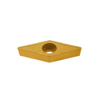
Two platforms dominate this segment in European and Asian job shops: the Sandvik CoroMill 390 and the Iscar Heli2000. Both are single-sided, positive-rake, 90° shoulder cutters with indexable inserts, and both are sold as general-purpose tools for steel, stainless and cast iron. Beneath that similarity the two designs take different routes: one relies on a serrated insert seat and a compact 90° corner geometry, the other on a helical cutting edge and a dovetail clamping pocket. This article compares the architecture, insert grades, cutting data and practical limits of both so you can decide which platform fits a given workpiece rather than a catalogue page.
Design Architecture: Two Answers to the Same Problem
The core challenge in 90° milling is that the cutting edge must be supported at the corner where bending stress peaks. A positive insert with a true 90° corner has very little material behind the tip, so the pocket has to locate the insert precisely and hold it against both radial and axial loads. CoroMill 390 solves this with the iLock serrated interface: radial and axial serrations on the insert underside mesh with the pocket, so the insert cannot creep under load and the corner stays where the programmer put it. Heli2000 solves the same problem with a dovetail pocket and a helical edge that spreads the entry shock across a longer section of carbide.
CoroMill 390 inserts are double-sided in some variants of the family and single-sided in the shoulder-milling versions; Heli2000 inserts are single-sided but indexed on four corners in the square sizes. Both are clamped by a top screw, which keeps the body simple and allows dense tooth counts on small diameters.
| Feature | Sandvik CoroMill 390 | Iscar Heli2000 |
|---|---|---|
| Insert sizes (typical) | 390-11 (iC 11 mm), 390-16 (iC 16 mm) | APKT 1003, APKT 1604, ADKT for aluminium |
| Maximum depth of cut | Up to 10 mm with -11 inserts, up to 16 mm with -16 inserts | Up to 10 mm with 1003, up to 16 mm with 1604 |
| Insert seating | iLock serrated interface, top screw | Dovetail pocket, top screw |
| Cutting edge form | Straight 90° corner with reinforced edge prep | Helical edge with progressive entry |
| Rake geometry | Positive axial and radial rake, light-cutting options | Positive rake, helical edge raises effective rake at entry |
| Typical diameter range | 40–160 mm shell and face mills, plus end mill versions | 16–50 mm end mills, 50–160 mm shell mills |
| Coolant | Internal coolant through body on most sizes | Internal coolant optional, external recommended for deep pockets |
| Wiper option | Yes, dedicated wiper inserts for floor finish | Yes, wiper and finishing geometries in the family |
Cutting Mechanics: Corner Load vs Helical Entry
The CoroMill 390 geometry is built around a stiff corner. The insert presents a relatively short, straight cutting edge to the work, so when the tooth enters the material the load rises quickly and stays concentrated near the 90° tip. That is efficient in stable setups and on rigid machines, because the force direction is predictable and the wall stays square. In unstable setups, on long overhangs or on thin-walled parts, the same concentration produces chatter and corner chipping unless feed per tooth and radial engagement are reduced.
Heli2000 takes the opposite approach. Its helical cutting edge engages the workpiece progressively from the leading corner, so the chip load ramps up over a few millimetres of edge instead of stepping on at once. The result is a softer entry, less impact on the spindle and lower noise at the same metal removal rate. The trade-off is a slightly higher axial force component and a more complex edge to regrind or inspect. In practice, Heli2000 tends to be more forgiving in 40-taper machines and in fixtures that are less than perfectly rigid, while CoroMill 390 rewards a well-clamped workpiece with very high productivity.
Both cutters are affected by chip thinning, and the effect is larger than most programmers expect. For a 90° cutter the average chip thickness is approximately:
hm ≈ fz × sin κr × √(ae / D)
With κr = 90°, sin κr = 1, so the correction depends only on the radial engagement ratio. At full slotting the programmed feed per tooth equals the chip thickness. At ae = 0.5D the actual chip is only about 71% of the programmed value, and at ae = 0.25D it is about 50%. Programming the same fz across all widths therefore overloads the edge in full cuts and underloads it in light finishing passes.
Insert Grades and Coatings
Grade choice matters more than the body on mixed production. Both suppliers offer PVD grades for toughness and sharp edges, CVD grades for abrasive steel and cast iron, and uncoated or diamond-like options for aluminium. The table below maps the common options; always confirm the current grade designation against the supplier’s programme, because both companies revise coating stacks regularly.
| Application | Sandvik grade | Iscar grade | Coating / substrate logic |
|---|---|---|---|
| Carbon and alloy steel, continuous | GC3330 | IC5400 | CVD TiCN + Al2O3, wear resistant |
| Steel, interrupted or roughing | GC2030 | IC808 | PVD TiAlN, tough substrate, strong edge |
| Stainless steel | GC1030 | IC908 | PVD, smooth coating to limit built-up edge |
| Cast iron | GC4330 | IC5400 / IC928 | CVD, alumina for abrasion resistance |
| Aluminium | GC530 or uncoated | IC20 or uncoated | Polished, high rake, no Al pick-up |
| Titanium and superalloys | GC1030 / GC2030 | IC830 / IC908 | PVD, sharp edge, low thermal load |
For steel at 180–250 HB, the CVD route generally gives the lowest cost per cubic centimetre in continuous cutting, while the PVD route wins wherever the cutter sees interrupted edges, cast skins or weld seams. In stainless steel the deciding factor is usually built-up edge: a smooth PVD coating and a sharp, positive edge reduce the tendency to smearing far more than a harder coating helps. In aluminium, neither CVD nor standard PVD belongs on the tool; polished uncoated inserts with high rake and generous chip room are the correct choice.
Cutting Data Comparison
The tables below give realistic starting values for a rigid 40-taper or larger machine with good coolant supply. They assume a 50 mm cutter, arbor mounting, and a workpiece that is properly supported. Reduce Vc by 15–20% for long overhangs, thin walls or unstable fixtures.
Carbon and Alloy Steel (180–250 HB)
| Parameter | CoroMill 390-11, GC3330 | CoroMill 390-16, GC3330 | Heli2000 1003, IC5400 | Heli2000 1604, IC5400 |
|---|---|---|---|---|
| Cutting speed Vc (m/min) | 220–280 | 200–260 | 200–260 | 180–240 |
| Feed per tooth fz (mm) | 0.12–0.20 | 0.15–0.25 | 0.10–0.18 | 0.15–0.25 |
| Axial depth ap (mm) | 2–8 | 3–12 | 2–8 | 3–12 |
| Radial width ae (% of D) | 30–70 | 30–70 | 25–60 | 30–70 |
Stainless Steel 304 / 316L
| Parameter | CoroMill 390, GC1030 | Heli2000, IC908 |
|---|---|---|
| Cutting speed Vc (m/min) | 120–170 | 110–160 |
| Feed per tooth fz (mm) | 0.08–0.15 | 0.08–0.14 |
| Axial depth ap (mm) | 2–6 | 2–6 |
| Radial width ae (% of D) | 25–50 | 25–50 |
Grey Cast Iron GJL 200–250
| Parameter | CoroMill 390, GC4330 | Heli2000, IC5400 |
|---|---|---|
| Cutting speed Vc (m/min) | 220–320 | 200–300 |
| Feed per tooth fz (mm) | 0.12–0.22 | 0.12–0.20 |
| Axial depth ap (mm) | 3–10 | 3–10 |
| Radial width ae (% of D) | 40–75 | 40–75 |
Aluminium and Titanium
| Material | Cutting speed Vc (m/min) | Feed per tooth fz (mm) | Notes |
|---|---|---|---|
| Aluminium 6061 / 7075 | 500–1000 | 0.10–0.25 | Polished uncoated inserts, high rake, flood or MQL |
| Titanium Ti-6Al-4V | 40–70 | 0.06–0.12 | PVD sharp edge, high-pressure coolant, no dwell |
Feed Correction for Radial Engagement
Use the table below to convert a target chip thickness into a programmed feed per tooth. Read the factor for the radial engagement ratio, then divide the desired hm by that factor. This is the single most effective adjustment when moving a cutter from a full-width cut to a shoulder cut or a light finishing pass.
| ae / D | 0.10 | 0.25 | 0.50 | 0.75 | 1.00 |
|---|---|---|---|---|---|
| Chip thinning factor (90° cutter) | 0.32 | 0.50 | 0.71 | 0.87 | 1.00 |
| Programmed fz for hm = 0.10 mm | 0.31 | 0.20 | 0.14 | 0.115 | 0.10 |
| Programmed fz for hm = 0.15 mm | 0.47 | 0.30 | 0.21 | 0.17 | 0.15 |
The correction has a hard limit. Once the programmed feed per tooth exceeds roughly 0.35 mm on an 11 mm insert, edge strength and spindle load become the constraint, not chip thinning. At that point widen ae or increase ap instead of pushing feed further.
Ramping, Helical Entry and Slotting
Neither cutter is a plunge mill, so entry strategy determines whether the first ten seconds of the cycle chip an insert. Both platforms tolerate a modest ramp angle when cutting a closed pocket, and both can helical-interpolate a bore. Conservative starting values are shown below; check the current technical guide before programming at the upper limit.
| Operation | CoroMill 390 | Heli2000 | Comment |
|---|---|---|---|
| Ramp angle, full width | ≤ 5° | ≤ 6° | Reduce to 3° in stainless and titanium |
| Ramp angle, 50% width | ≤ 8° | ≤ 10° | Ramp along the wall, not into a corner |
| Helical pitch | 0.5–1.0 mm/rev | 0.5–1.0 mm/rev | Keep pitch below 0.5 × ap limit |
| Full slot, ap | ≤ 0.5 × D | ≤ 0.5 × D | Use trochoidal path for deep slots |
| Plunge | Not recommended | Not recommended | Pre-drill or ramp instead |
For deep shoulders, a stepped pass with ap equal to the insert’s rated depth is more productive than a single shallow pass at high feed, because the number of entries per part drops. Each entry is an impact event; fewer entries means fewer chipped corners.
Power and Removal Rate: A Worked Example
Take a 50 mm, 4-tooth CoroMill 390 in 42CrMo4 at 250 HB. Cutting speed 250 m/min gives:
- Spindle speed: n = 1000 × 250 / (π × 50) ≈ 1592 rpm
- Feed per tooth 0.15 mm at ae = 0.5D (factor 0.71) gives hm ≈ 0.107 mm
- Table feed: vf = 1592 × 4 × 0.15 ≈ 955 mm/min
- With ap = 5 mm and ae = 25 mm: MRR = 25 × 5 × 955 ≈ 119,400 mm³/min
Specific cutting force for alloy steel at this chip thickness is roughly 2,600 N/mm², so the net cutting power is:
Pc = ae × ap × vf × kc / (60 × 106) ≈ 5.2 kW
At 80% spindle utilisation the machine needs at least 6.5 kW at the spindle, plus margin for the momentary peaks of an interrupted cut. A 7.5 kW spindle is therefore the realistic minimum for this pass. The same calculation on a 40-taper machine with a 5.5 kW spindle shows why ap must drop to 3 mm or ae to 15 mm before the cutter can run at the programmed feed.
Surface Finish and Wall Quality
Both cutters produce a square wall, but the finish depends on insert condition and wiper availability. With standard inserts, expect Ra 1.6–3.2 µm on steel and Ra 0.8–1.6 µm on cast iron at moderate feed. A dedicated wiper insert in the last position typically halves the Ra value and eliminates the feed-mark scallops that show up under a straight edge. The CoroMill 390 wiper programme is mature and widely stocked; Heli2000 offers wiper and finishing geometries within the same family, so a mixed body can run roughing and finishing inserts without changing the cutter.
Wall squareness is a separate issue. A 90° cutter only produces a true 90° wall if the spindle is perpendicular to the table and the insert corner is intact. A chipped corner of 0.05 mm shows up as a 0.05 mm step at the wall-floor junction, which is often mistaken for a machine alignment problem. Inspect the corner radius before adjusting the machine.
Wear Behaviour and Troubleshooting
| Symptom | Likely cause | Correction |
|---|---|---|
| Corner chipping on entry | Feed too low, rubbing before engagement | Raise fz by 20–30%, use tougher grade |
| Flank wear concentrated at the tip | Speed too high for the grade | Reduce Vc by 15%, check coolant direction |
| Built-up edge in stainless | Sharp edge breakdown, low speed | PVD grade, raise speed, increase feed |
| Notch wear at depth line | Work-hardened layer, cast skin | Vary ap between passes, increase edge prep |
| Thermal cracks | Intermittent coolant on hot edge | Flood continuously or run dry, never intermittent |
| Chatter marks on wall | Radial force too high, weak setup | Reduce ae, increase tooth count, stiffen fixture |
| Insert movement / size drift | Pocket contamination or worn screw | Clean seat, replace screw at each index |
Which Platform Fits Which Job
| Scenario | Recommended platform | Reason |
|---|---|---|
| Rigid 50-taper, high-volume steel | CoroMill 390 | Stiff corner, high feed capability, broad grade range |
| 40-taper or older machine, mixed work | Heli2000 | Progressive helical entry tolerates less rigid setups |
| Thin-wall components | Either, reduced ae | Radial force is the limiting factor, not the brand |
| Deep shoulders, 10–16 mm | CoroMill 390-16 / Heli2000 1604 | Larger insert size covers depth in fewer passes |
| Aluminium, high speed | Either with polished uncoated inserts | Geometry and polish matter more than the body |
| Stainless and duplex | Either with PVD grade | Sharp edge and smooth coating control BUE |
| Unattended lights-out running | CoroMill 390 | Predictable wear and mature wiper/finish options |
Practical Takeaways
- Match the entry to the machine. Heli2000’s helical edge is the safer choice where rigidity is uncertain; CoroMill 390’s stiff corner is the faster choice where the setup is solid.
- Correct the feed for radial engagement. A 90° cutter at 25% width needs roughly double the programmed fz to reach the same chip thickness as a full slot.
- Choose the grade by failure mode, not by material name. Continuous steel wants CVD; interrupted steel and stainless want PVD; aluminium wants polished uncoated.
- Control the entry. Ramp at 3–5° in difficult materials and avoid plunging; most corner damage happens in the first tooth engagement.
- Check the corner before blaming the machine. A 0.05 mm chip in the insert tip produces a 0.05 mm wall step that looks like misalignment.
Both cutters are capable of the same wall quality and, in the right grade, similar tool life. The decision usually comes down to machine rigidity, the depth of shoulder required and how much of the production is interrupted cutting. Test both platforms on the same part with the same target chip thickness, measure cycle time and insert cost per part over a full edge life, and the choice becomes a calculation rather than a preference.
Shop Related Products at HOOGUU