Back-Boring Operations: Reverse Toolpath and Insert Selection
Back-boring (also called back-spotfacing or reverse boring) is the operation of machining a surface, counterbore, or chamfer on the far side of a workpiece feature, accessed through a pre-existing hole. This operation is essential for creating mounting surfaces, counterbores for fastener heads, and sealing surfaces on the back face of housings, flanges, and structural components. Because the cutting tool must reach through the access hole and cut on the opposite side, back-boring presents unique challenges in tool design, toolpath programming, and chip management.
Back-Boring Tool Types
Three primary tool categories are used for back-boring operations:
Swing-out back boring tools: These tools have a retractable cutting head that passes through the access hole in a collapsed state, then swings or slides out to the cutting position once it clears the far side. Available for counterbore diameters from 16 mm to 80 mm, they are the most versatile option. The swing-out mechanism is actuated by coolant pressure, centrifugal force, or a mechanical pull-push mechanism integrated into the toolholder.
Fixed-blade back boring tools: These tools have a permanently extended cutting head with a cutting diameter larger than the shank but requiring the access hole to be large enough for the cutting head to pass through. This limits their use to situations where the access hole is at least 60 to 70 percent of the back-bore diameter. They are simpler and more rigid than swing-out tools but less versatile.
Reverse-counterbore tools (Heule style): These specialized tools use a spring-loaded or coolant-actuated blade that extends through the far side of the workpiece. The blade retracts when the tool is pulled back through the hole. Available for counterbore diameters from 12 mm to 60 mm, they are widely used in automotive and aerospace production for back-spotfacing operations.
Insert Selection for Back-Boring
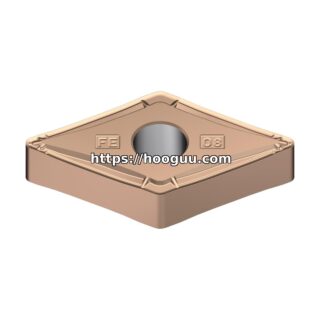
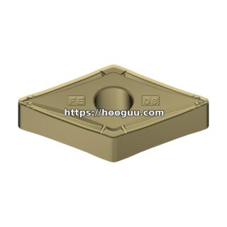
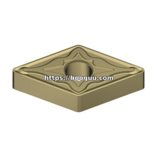
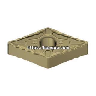
Back-boring inserts are typically smaller than standard boring inserts due to the space constraints of the tool mechanism. Common insert types include CCMT 06 and 07, DCMT 07, and VBMT 11. The insert must be mounted in a reversed orientation compared to standard boring, with the cutting edge facing toward the spindle (away from the workpiece far side).
For steel workpieces, use PVD-coated TiAlN inserts in the P15 to P25 grade range with positive rake geometry. Positive rake is particularly important in back-boring because the tool mechanism is less rigid than a standard boring bar, and cutting forces must be minimized. For aluminum and non-ferrous materials, uncoated polished carbide inserts with high rake angles (15 to 25 degrees) prevent built-up edge formation on the reversed cutting geometry.
Cutting Parameters
Back-boring cutting speeds are typically 20 to 30 percent lower than standard boring speeds due to the reduced rigidity of the tool mechanism. For a swing-out back boring tool with a 32 mm cutting diameter:
- Carbon steel (1045): Cutting speed 100 to 140 m/min (955 to 1,337 RPM). Feed per tooth or per revolution: 0.05 to 0.10 mm/rev. Depth of cut (axial): 0.5 to 2.0 mm per pass. Maximum of 3 to 4 passes to reach full counterbore depth.
- Stainless steel (304): Cutting speed 60 to 90 m/min. Feed: 0.03 to 0.07 mm/rev. Depth per pass: 0.3 to 1.0 mm. Flood coolant mandatory to prevent work hardening.
- Aluminum (6061-T6): Cutting speed 180 to 300 m/min. Feed: 0.08 to 0.18 mm/rev. Depth per pass: 0.5 to 3.0 mm. MQL or flood coolant acceptable.
- Cast iron (GG25): Cutting speed 90 to 140 m/min. Feed: 0.06 to 0.12 mm/rev. Depth per pass: 0.5 to 2.0 mm. Air blast or minimal coolant.
Toolpath Programming
Back-boring toolpaths must account for the tool deployment and retraction sequence. A typical back-boring cycle on a machining center follows these steps:
- 1. Position the tool above the access hole
- 2. Feed the tool through the access hole at rapid or high feed rate (no cutting)
- 3. Once the cutting head clears the far side of the workpiece, deploy the cutting mechanism (swing out, extend blade)
- 4. Feed axially into the back surface at the programmed cutting feed rate
- 5. Complete the required number of passes to reach the counterbore depth
- 6. Retract the cutting mechanism (collapse the tool)
- 7. Retract the tool back through the access hole at rapid rate
On CNC lathes, back-boring is performed by feeding the tool through the bore from the tailstock side (or using a rear turret station) and cutting on the pull stroke. The tool feeds in the negative Z direction while the workpiece rotates. Programming considerations are similar to standard boring but with reversed axis directions.
Chip Management
Chips from back-boring fall into the interior of the workpiece cavity or bore, where they can accumulate and interfere with subsequent operations. In production, it is essential to clear chips between parts. Methods include inverting the workpiece and tapping it to dislodge chips, using an air blast through the access hole, or programming a coolant flush cycle after the back-boring operation. For blind internal cavities, consider adding a chip drain hole in the workpiece design if the function permits.
Accuracy and Surface Finish
Back-boring accuracy is inherently lower than standard boring due to the longer effective tool length and less rigid tool mechanism. Typical achievable tolerances are plus or minus 0.05 to 0.10 mm on counterbore diameter and plus or minus 0.03 to 0.05 mm on counterbore depth. Surface finish ranges from Ra 1.6 to 3.2 micrometers depending on the insert condition and cutting parameters. For critical sealing surfaces, a finishing pass at reduced feed (50 percent of roughing feed) improves surface quality to Ra 0.8 to 1.6 micrometers.
Summary
Back-boring requires specialized tools with deployable cutting mechanisms that reach through access holes to machine far-side surfaces. Swing-out tools offer the most versatility, while fixed-blade and reverse-counterbore tools provide simpler solutions for specific applications. Reduce cutting speeds and feeds compared to standard boring to compensate for tool mechanism limitations, and manage chip accumulation in the workpiece interior. With proper tool selection and parameters, back-boring achieves acceptable accuracy for most counterbore and back-spotfacing applications.
Shop Related Products at HOOGUU