

Introduction
Copper and its alloys rank among the most widely engineered non-ferrous metals in modern manufacturing. From electrical connectors and heat exchangers to marine propellers and plumbing components, copper alloys combine excellent conductivity, corrosion resistance, and machinability when properly approached. Yet many machinists treat all copper family members identically — a costly oversimplification. Free-cutting brass machines like butter, but phosphor bronze and pure copper behave very differently under the same tool.
This guide walks through the three major copper alloy families, their unique chip-formation characteristics, recommended cutting parameters across turning, milling, and drilling, and practical strategies for controlling the long stringy chips that copper is notorious for. We compare commercial tooling platforms from Sandvik, Iscar, Seco, and Korloy, and provide parameter tables you can drop straight into your program.
1. Copper Alloy Family Quick Reference
The term “copper alloys” covers more than 50 commercially significant compositions. For machining purposes, grouping by chip behavior is more useful than strict metallurgical classification.
1.1 Alloy Composition and Machinability Rating
| Alloy Family | Common Designations | Lead Content | Hardness HB | Machinability | Chip Type |
|---|---|---|---|---|---|
| Free-Cutting Brass | C36000, C37700, CW617N | 2.5–3.7% | 80–110 | 90–100% (reference) | Short, fragmented |
| Leaded Brass | C34000, C35000 | 1.4–2.0% | 90–120 | 70–85% | Short → tubular |
| Naval Brass | C46400, C46200 | ≤0.5% | 100–130 | 55–70% | Long, stringy |
| Bronze (Tin Bronze) | C93200, C95400 | ≤0.2% | 110–190 | 45–65% | Long, stringy |
| Phosphor Bronze | C51000, C54400 | 0% | 110–200 | 35–55% | Very long, springy |
| Pure Copper (OFC) | C10100, C11000 | 0% | 70–90 | 20–40% | Continuous, stringy |
| Aluminum Bronze | C95400, C95500 | 0% | 150–220 | 30–50% | Long, segmented |
Machinability note: The rating above uses free-cutting brass C36000 as 100%. Pure OFC copper sits at the bottom of the scale because its face-centered cubic crystal structure permits enormous plastic deformation before fracture — chips do not break, they coil into meter-long ribbons that tangle around tool holders and workpieces. Lead acts as an internal lubricant: tiny Pb particles smear across the tool-chip interface, reducing friction and promoting chip fracture. This is why leaded brass machines dramatically better than lead-free brass of otherwise similar composition.
1.2 Key Machining Challenges by Alloy
| Challenge | Free-Cutting Brass | Bronze / Phosphor Bronze | Pure Copper | Aluminum Bronze |
|---|---|---|---|---|
| Chip Control | Minimal | Moderate | Severe | Moderate |
| Built-Up Edge | None | Low | High | Medium |
| Tool Wear | Very Low | Low–Medium | Low | Medium–High |
| Surface Finish Risk | Minimal | Low | High (tearing) | Medium |
| Power Demand | Low | Medium | Medium | High |
2. Tool Material and Coating Selection
Copper alloys are non-ferrous, so the high-temperature deformation that limits carbide life in steel cutting is not a dominant failure mode. Instead, adhesion, abrasion (from hard intermetallic phases in bronzes), and edge rounding govern tool selection.
2.1 Recommended Tool Materials
| Tool Material | Grade Example | Best For | Relative Tool Life | Surface Finish |
|---|---|---|---|---|
| Uncoated Cemented Carbide (WC-Co) | K10, K20, Sandvik H10F, Iscar IC08 | Brass, pure copper turning/milling — excellent adhesion resistance | 1.0× (reference) | Good |
| TiN Coated Carbide | TiN, TiCN single layer | Bronze, aluminum bronze, medium production | 1.3–1.8× | Good |
| Diamond-Like Carbon (DLC) | Seco JibroDLC, Sandvik CoroMill Plura DLC | Pure copper, phosphor bronze — ultra-low adhesion | 2.5–4× | Excellent |
| Polycrystalline Diamond (PCD) | PCD edge brazed inserts | Aluminum bronze, high-volume pure copper | 5–10× | Mirror finish |
| High-Speed Steel (HSS) | M35, M42 (cobalt) | Low-volume brass drilling, threading | 0.3–0.5× | Fair |
2.2 Why Uncoated Carbide Often Outperforms PVD for Copper
This surprises many machinists. For steel, CVD and PVD coatings provide thermal barriers and abrasive wear resistance that uncoated carbide cannot match. For copper, the opposite is often true. Here is why:
- Adhesion vs. Abrasion: Copper does not generate the cutting temperatures (>800°C) that soften carbide binders in steel. Copper wear is primarily adhesive — copper atoms stick to the tool surface and pull out carbide grains. PVD coatings such as TiAlN actually have higher chemical affinity for copper than bare WC-Co does, leading to more built-up edge, not less.
- DLC Exception: Diamond-like carbon is the one coating family that dramatically improves copper machining. DLC has a graphite-like layered structure with extremely low surface energy, preventing copper adhesion entirely. Seco reports 3–5× tool life improvement on pure copper end mills compared to uncoated carbide.
- PCD for Abrasive Bronzes: Aluminum bronze (C954, C955) contains hard intermetallic Al2Cu phases that abrade carbides. Here PCD’s extreme hardness (8,000 HV vs. 1,800 HV for carbide) provides unmatched life.
3. Cutting Parameters Reference
All values below use solid carbide tools, dry machining (compressed air recommended), and represent a starting point. Fine-tune by ±15% based on specific machine rigidity and tool overhang.
3.1 Turning Parameters — Insert Grade: Uncoated K20 / Sandvik H10F
| Alloy | Operation | Vc (m/min) | fz (mm/rev) | ap (mm) | Chip Expectation |
|---|---|---|---|---|---|
| Free-Cutting Brass | Roughing | 450–800 | 0.25–0.40 | 2–4 | Short C-chips |
| Finishing | 700–1200 | 0.08–0.15 | 0.5–1.0 | Short spiral | |
| Naval Brass (C464) | Roughing | 300–500 | 0.20–0.35 | 2–3 | Short tubular |
| Finishing | 500–800 | 0.08–0.12 | 0.5–1.0 | Tubular | |
| Phosphor Bronze (C510) | Roughing | 250–400 | 0.18–0.30 | 1.5–2.5 | Long, springy |
| Finishing | 400–600 | 0.06–0.10 | 0.3–0.8 | Long stringy | |
| Pure Copper (C1100) | Roughing | 200–350 | 0.15–0.25 | 1.5–2.5 | Continuous ribbon |
| Finishing | 300–500 | 0.05–0.10 | 0.3–0.8 | Long continuous | |
| Aluminum Bronze (C954) | Roughing | 150–250 | 0.12–0.22 | 1.0–2.0 | Long segmented |
| Finishing | 250–400 | 0.05–0.08 | 0.2–0.5 | Short segmented |
3.2 Milling Parameters — End Mill, 2-Flute Solid Carbide Uncoated
| Alloy | Vc (m/min) | fz (mm/tooth) | ae (% of Oslash;) | ap (mm) | Compressed Air |
|---|---|---|---|---|---|
| Free-Cutting Brass | 500–900 | 0.15–0.25 | 50–100% | 1.0×Oslash; | Optional |
| Leaded Brass (C340) | 350–600 | 0.12–0.20 | 50–100% | 0.8×Oslash; | Optional |
| Naval Brass (C464) | 280–450 | 0.10–0.18 | 40–80% | 0.5×Oslash; | Recommended |
| Phosphor Bronze (C510) | 220–380 | 0.08–0.15 | 30–60% | 0.5×Oslash; | Essential |
| Pure Copper (C1100) | 180–300 | 0.08–0.14 | 30–50% | 0.3×Oslash; | Essential |
| Aluminum Bronze (C954) | 140–240 | 0.08–0.14 | 30–50% | 0.5×Oslash; | Recommended |
Slotting note: When full-slotting (ae = 100% diameter), reduce Vc by 20–30% to compensate for reduced tool escape. For pure copper, consider trochoidal toolpaths even when slotting — the light radial engagement and continuous cutter engagement dramatically improve chip evacuation compared to full-slot climb milling.
3.3 Drilling Parameters — Solid Carbide Drill, Uncoated K20
| Alloy | Vc (m/min) | Feed (mm/rev) | Coolant | Peck Cycle |
|---|---|---|---|---|
| Free-Cutting Brass | 250–400 | 0.15–0.30 | Dry / Air | Not needed |
| Leaded Brass | 200–320 | 0.12–0.25 | Dry / Air | Not needed |
| Naval Brass | 150–250 | 0.10–0.18 | Air or MQL | L/D > 5:1 use peck |
| Phosphor Bronze | 120–200 | 0.08–0.15 | Air or MQL | Peck at L/D > 3:1 |
| Pure Copper | 100–180 | 0.06–0.12 | Air or MQL | Peck at L/D > 3:1 |
| Aluminum Bronze | 80–140 | 0.06–0.10 | MQL or Flood | Peck at L/D > 4:1 |
Drill geometry note: Standard 118 degree point angle HSS drills work acceptably for brass, but solid carbide drills with a 140 degree split point reduce thrust forces by 25–30% in tough copper alloys and improve centering accuracy. Iscar’s SumoCham and Sandvik’s CoroDrill 460 both offer copper-optimized point geometries with polished flutes to prevent chip adhesion.
4. Chip Control Strategies — The Copper Machinist’s Daily Battle
The #1 frustration in copper machining is chips that do not break. When an 8-meter copper ribbon wraps around your tool holder mid-turn, it is not just messy — it can snap the insert, damage the workpiece surface, and injure the operator. Here is a hierarchical approach to chip control, ordered by practical implementation effort.
4.1 Chipbreaker Insert Geometry — The First Line of Defense
| Platform | Insert Type | Geometry | Application | Chip Quality |
|---|---|---|---|---|
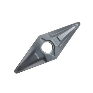
| Sandvik Coromant | CNMG / DNMG with -LM breaker | Narrow land, steep breaker angle | Naval brass, phosphor bronze turning | Short tubular |
| Sandvik Coromant | Wiper insert -WG | Flat wiper nose radius | Fine finishing pure copper | Short spiral + mirror surface |
| Iscar | TNMG / CNMG with M3M geometry | Variable breaker depth | Pure copper roughing | Broken C-chips at higher fz |
| Iscar | EN/GN groove turn inserts | Integrated chip former | All copper alloys grooving | Controlled, short |
| Seco | DNMG with MP3000 geometry | Rounded breaker edge | Aluminum bronze roughing | Good chip break + low edge stress |
| Korloy | CNMG with -HM chipbreaker | Deep narrow groove | Phosphor bronze heavy cuts | Short, controlled |
4.2 Parameter Tuning for Chip Breaking
If your chips are still stringy despite the right geometry, adjust in this order:
- Increase feed per revolution (fz) by 20–30%. Copper work-hardens as it deforms. Higher fz produces a thicker chip that fractures more easily. Do not exceed the insert’s strength rating.
- Reduce cutting speed (Vc) by 15%. Lower Vc means shorter chip formation time, giving the chip less opportunity to plastically deform into a continuous ribbon. This is especially effective for pure copper.
- Apply a slight depth-of-cut oscillation (peck turning). Add a small programmed variation (+/- 0.05 mm) to ap every 3–5 revolutions. The interrupted shear plane creates a natural chip fracture point.
4.3 Compressed Air and Coolant Strategy
Unlike steel and stainless, copper machining does not generate enough heat to demand flood coolant — temperatures rarely exceed 250 degrees C at the tool tip, even at high Vc. However, air blast serves a critical purpose: chip evacuation.
- Brass and Naval Brass: Dry machining with a single air nozzle pointed at the chip flow direction is sufficient.
- Phosphor Bronze and Pure Copper: Two opposed air nozzles (180 degrees apart, both pointing into the cut) create a shear that breaks long ribbons into manageable lengths. 6–8 bar pressure minimum.
- MQL Option: For high-volume production, minimum quantity lubrication (5–20 mL/h of biodegradable oil) reduces BUE formation on both uncoated and DLC tools while providing better visibility than flood coolant.
- Flood Coolant: Only justified for aluminum bronze, where the intermetallic Al-Cu phases cause abrasive wear. Use a synthetic fluid with excellent lubricity (5–10% concentration), not a semi-synthetic or straight mineral oil.
5. Tool Wear Diagnosis for Copper Alloys
Copper-induced tool wear looks different from steel-induced wear. Learn to spot the patterns before they cause scrap.
| Wear Mode | Appearance | Alloy Most Likely | Root Cause | Corrective Action |
|---|---|---|---|---|
| Built-Up Edge (BUE) | Dull, ragged cutting edge with copper adhering | Pure copper, phosphor bronze | Low Vc + uncoated tool | Increase Vc by 30%; switch to DLC or PCD |
| Flank Wear | Uniform wear land on flank face | Aluminum bronze, tin bronze | Abrasive hard particles + high Vc | Reduce Vc by 15%; use PCD insert |
| Nose Rounding | Loss of sharp nose radius, poor surface finish | All copper alloys | General wear; too high Vc for too long | Change inserts earlier than steel (70% of steel life) |
| Crater Wear | Dissolution on rake face near edge | Pure copper at Vc > 500 m/min | Copper diffusion into WC binder | Reduce Vc; use DLC-coated tool |
| Micro-Chipping | Small edge breakouts on cutting edge | Bronze alloys with peck cycles | Interrupted cutting + brittle geometry | Use honed edge preparation (K-factor 1.2–1.5) |
6. Surface Finish and Dimensional Accuracy
Copper alloys are valued for electrical and sealing applications, both of which require excellent surface integrity. Follow these rules to consistently achieve Ra under 1.6 microns and avoid costly rework.
6.1 Roughness Prediction by Tool Nose Radius
For turning, the arithmetic roughness Ra (in microns) is approximately Ra approx f-squared divided by (32 times r-epsilon) times 1000, where f is feed per revolution (mm/rev) and r-epsilon is the insert nose radius (mm).
| Insert Nose Radius (r epsilon) | fz = 0.10 mm/rev | fz = 0.15 mm/rev | fz = 0.20 mm/rev |
|---|---|---|---|
| 0.4 mm | Ra 0.78 micron | Ra 1.76 micron | Ra 3.13 micron |
| 0.8 mm | Ra 0.39 micron | Ra 0.88 micron | Ra 1.56 micron |
| 1.2 mm | Ra 0.26 micron | Ra 0.59 micron | Ra 1.04 micron |
Wiper inserts note: Standard radius inserts follow the table above. Wiper inserts (Sandvik -WG, Iscar WIPER, Seco WX) improve Ra by 40–60% at the same fz — a 0.8 mm radius wiper at fz = 0.15 mm/rev delivers Ra ~0.35 micron, comparable to a 1.2 mm standard radius at fz = 0.10 mm/rev. For sealing surfaces on pure copper and phosphor bronze, wiper inserts with a light final pass (ap = 0.05–0.10 mm, Vc = 400–600 m/min) are standard practice.
6.2 Crystallographic Tearing in Pure Copper
Pure OFC copper (C10100, C11000) is single-phase FCC, and if the cutting edge is slightly dull or fz is too low, the tool does not shear the material cleanly — it tears individual grains out, leaving a matte, uneven surface. This is the most common finish defect in copper electrical connectors.
Prevention checklist:
- Use a sharp, freshly edged insert. Dulling beyond VB = 0.1 mm guarantees tearing.
- Apply a hone of K-factor 0.8–1.2 (very light edge preparation). No hone = edge chips immediately; heavy hone = edge is too blunt for shearing.
- Feed must be fz >= 0.08 mm/rev. Lower fz causes the tool to rub instead of cut.
- Air blast exactly on the cutting edge to prevent BUE.
7. Brand Platform Comparison — Copper-Optimized Tooling
Every major cutting tool manufacturer now offers copper-specific geometries and coatings. Here is a practical comparison of four market leaders.
| Brand | Platform | Insert Grade | Geometry | Strength | Weakness |
|---|---|---|---|---|---|
| Sandvik | CoroTurn 107 / H10F uncoated | H10F (WC-Co, 6% Co) | CNMG-LM, DNMG-LG chipbreakers | Best-in-class pure copper chip control; balanced wear resistance | Premium pricing; some geometries not stocked for small lathes |
| Sandvik | CoroMill Plura DLC end mills | DLC coated K10 body | 2-flute, 30 degree helix, polished flutes | 4x life vs uncoated; excellent for pure copper slotting | High initial cost; DLC wears through at Vc > 400 m/min in aluminum bronze |
| Iscar | TNMG / CNMG-M3M grooving | IC08 uncoated / IC20 TiN | M3M variable chipbreaker depth | Excellent grooving and threading on all copper alloys | General turning geometries slightly below Sandvik for pure copper finish |
| Iscar | SumoCham drill | IC908 PVD coated | 140 degree split point, polished flutes | Best-in-class drill for pure copper; minimal work hardening | PVD coating can cause slight BUE on pure copper — use air blast |
| Seco | JabroDLC end mills | DLC coated K20 body | 2–3 flutes, 35 degree helix | Outstanding surface finish; DLC consistency across all diameters | Slightly lower chip evacuation than Sandvik Plura for deep slotting |
| Korloy | CNMG / DNMG-HM | PC5400 uncoated / PC5300 TiCN | HM deep chipbreaker | Deep grooving on phosphor bronze and aluminum bronze | Limited literature on pure copper performance |
Bottom line for brand selection: For pure copper finishing and electrical connector work, Sandvik H10F uncoated with wiper geometry is the reference. For phosphor bronze and aluminum bronze heavy roughing, Iscar M3M or Korloy HM chipbreakers provide superior chip fragmentation at high fz. For high-volume milling, both Seco JabroDLC and Sandvik Plura DLC deliver 3–4x tool life — choose whichever distributor has better local support.
8. Real-World Example — Copper Heat Exchanger Tube Nipples
Let us work through a complete setup for turning C12200 phosphorus deoxidized copper nipples (diameter 16 mm x 30 mm, Ra under 1.6 micron required on OD sealing surface).
Machine: CNC lathe, 5 kW spindle, hydraulic chuck
Tool: Sandvik DNMG 110404-WG wiper insert, grade H10F uncoated
Workholding: Collet chuck for OD clamping; minimize overhang to 25 mm
| Step | Operation | Vc (m/min) | fz (mm/rev) | ap (mm) | Result |
|---|---|---|---|---|---|
| 1 | Face and chamfer | 300 | 0.15 | 0.5 | Clean face, no tear |
| 2 | Rough turn OD to 15.2 mm | 280 | 0.18 | 0.8 x 1.0 mm passes | Short C-chips, good chip flow |
| 3 | Finishing pass to 15.0 mm | 420 | 0.10 | 0.10 mm | Ra ~0.9 micron |
| 4 | Wiper pass on sealing length | 500 | 0.12 | 0.05 mm | Ra ~0.5 micron (leak-tight verified) |
| 5 | Part-off to 30 mm length | 250 | 0.10 | — | Clean parting, no burr |
Run summary: 220 parts per insert edge; consistent Ra throughout; no BUE observed. Tool life ends at VB = 0.15 mm flank wear, well before any surface degradation. Compare this to the user’s previous HSS setup: 25 parts per edge, Ra ~2.5 micron, 2–3 hours of operator intervention per batch to clear chip tangles.
9. Common Mistakes and How to Avoid Them
| Mistake | Typical Outcome | Solution |
|---|---|---|
| Using TiAlN-coated inserts for pure copper finishing | Severe BUE, poor Ra, 50% lower tool life than uncoated | Switch to uncoated K10/K20 or DLC-coated tool |
| Running pure copper at steel cutting speeds (Vc > 600 m/min) | Crater wear and diffusion at tool tip; catastrophic edge failure | Stay at Vc <= 500 m/min for pure copper; <= 350 m/min for aluminum bronze |
| Single air nozzle for phosphor bronze | Chips wrap around tool holder every 10–15 seconds | Add a second opposed nozzle; use peck turning oscillation |
| Worn insert (VB > 0.2 mm) on pure copper | Grain tearing, matte surface, dimensional drift | Change at VB = 0.1 mm — copper demands 50% earlier insert changeover than steel |
| 118 degree HSS drill for pure copper deep drilling (L/D > 5:1) | Chips pack flute; drill snaps at breakthrough | Switch to 140 degree split point carbide drill with polished flutes; mandatory peck cycle |
| Treating free-cutting brass parameters for phosphor bronze | Stringy chips, power overload, tool breakage | Reduce Vc by 40–50%; reduce fz by 25–35% — copper alloys are NOT interchangeable |
10. Summary and Quick-Start Guide
Copper and its alloys reward respect for their diversity. The same machine that runs free-cutting brass at Vc = 800 m/min will produce tangled meters of ribbon on pure copper at half that speed. Here is the 30-second decision tree:
- Identify the alloy: Free-cutting brass (Pb > 2%) leads to aggressive parameters, dry air blast. Pure copper / phosphor bronze lead to conservative Vc, double air blast, peck cycles.
- Pick tool material: Uncoated K10/K20 carbide for 80% of jobs. DLC for production pure copper milling. PCD for aluminum bronze. HSS only for low-volume brass drilling.
- Start slow, increase Vc first: Copper forgives speed increases far better than feed decreases. Do not undercut; start at the midpoint of the Vc range in Table 3.1 and work up by 10% every 5–10 parts.
- Chip first, finish second: If chips are stringy, fix chipbreaker geometry and parameter tuning before worrying about surface finish. You cannot get Ra under 1.6 micron from a tool buried in a 2-meter copper ribbon.
- Change inserts earlier: Copper work-hardens locally at the tool tip, accelerating edge rounding. Change at VB = 0.1 mm (70% of steel’s 0.15 mm limit).
Follow these guidelines and copper machining becomes predictable, repeatable, and surprisingly fast — with tool lives that often exceed steel machining of equivalent hardness. Skip them, and you will spend half your shift untangling copper ribbons from your tool holder.
Shop Related Products at HOOGUU