
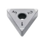



Thread milling has moved from a niche operation to a mainstream strategy on three-axis vertical machining centres. The reason is practical: one small-diameter carbide cutter can produce an internal or external thread in a part that is too large to tap, too expensive to scrap, or too close to a shoulder for a tap to reach. Among the tools specified for this work, two Israeli manufacturers dominate the mid-market: Carmex Precision Tools and Vargus, whose thread milling products are sold under the VARDEX brand.
This comparison looks at the two ranges from an application standpoint rather than a catalogue standpoint. It covers the two fundamental thread mill architectures, the product families each manufacturer offers, cutting data you can use as a starting point, and the programming arithmetic that decides whether the thread comes out to gauge.
Why Thread Milling Instead of Tapping or Thread Turning
Before comparing brands it is worth being clear about when thread milling is the correct process at all. Each of the three common thread production methods loads the workpiece differently, and that difference drives tool life, part accuracy and fixture cost.
| Criterion | Tapping | Thread turning | Thread milling |
|---|---|---|---|
| Tool engagement | Full 360 degrees, all teeth | Single point, continuous | Interrupted, one to three teeth |
| Cutting force direction | High torque, axial thrust | High radial force, part deflection | Low radial force, distributed |
| Thread size change | New tap per size and pitch | Programme change, same insert | Programme change, same tool (partial profile) |
| Large or irregular parts | Difficult, high torque | Requires a lathe | Straightforward on a VMC |
| Blind holes and shoulders | Limited by tap chamfer | Limited by run-out groove | Good, small radial clearance needed |
| Chip control in ductile steel | Poor, chips pack in flutes | Good | Excellent, short interrupted cuts |
| Thread repair in situ | Not practical | Not practical | Standard practice |
| Relative cycle time | Fastest | Slow | Moderate |
The low radial force is the key advantage. Because the cutter removes material in short arcs instead of a continuous chip, thin-walled parts and unsupported bores can be threaded without distortion. The trade-off is cycle time: a thread mill follows a helical path and cannot match the speed of a tap in a through hole in aluminium.
Full-Profile versus Partial-Profile Thread Mills
Every thread mill on the market belongs to one of two geometry families, and the choice between them matters more than the choice between brands.
Full-profile (multi-tooth) tools
A full-profile thread mill carries the complete thread form, crest to root, along a number of teeth arranged at exactly the required pitch. It produces the thread in a single helical pass. The tool is ground for one specific pitch and one specific thread standard, so an M10 x 1.5 tool cannot cut an M10 x 1.25 thread. Cycle time is the shortest of any thread milling method and thread form accuracy is excellent because the profile is ground into the tool, not generated by the machine path.
Partial-profile (single-point) tools
A partial-profile tool has a single thread-form tooth, or a small group of teeth at a pitch that does not match the workpiece. The thread is generated by the helical interpolation path, with the pitch supplied by the CNC programme. One tool covers a range of pitches, and coarse threads are cut in two to four radial passes. Cycle time is longer, but tool inventory is dramatically smaller and the same cutter can handle metric, UNC and special pitches.
| Feature | Full profile | Partial profile |
|---|---|---|
| Thread form source | Ground into the tool | Generated by the helical path |
| Pitch flexibility | One pitch per tool | Range of pitches per tool |
| Number of passes | One | Two to four for coarse pitches |
| Cycle time | Shortest | Longer, especially in coarse threads |
| Thread form accuracy | Highest | Good, depends on machine path |
| Tool inventory | Large, one tool per pitch | Small, one tool per diameter class |
| Typical use | Production batches, small threads | Repair, prototypes, large or special threads |
| Minimum thread diameter | Down to about M2 | Typically M6 and above |
Carmex Thread Milling Range
Carmex built its reputation on thread milling and grooving, and the Mill-Thread family is the core of the offer. The range is organised around solid carbide cutters with two to four flutes, available in internal and external versions and in left-hand and right-hand helix forms.
- Solid carbide thread mills cover roughly M2 to M20 in full-profile versions, with partial-profile single-point tools extending to large diameters and special pitches.
- Indexable thread mills use replaceable carbide inserts on a steel shank for diameters where a solid carbide tool would be uneconomic, typically above M20 and in pipe threads.
- Thread standards include ISO metric, UNC, UNF, BSP, NPT and NPTF, plus trapezoidal and special profiles on request.
- Coatings are typically AlTiN or TiAlN for steel and stainless, with polished uncoated grades for aluminium and copper alloys.
- Cooling is usually external, with through-tool coolant offered on selected internal-thread tools for deep bores.
Carmex cutters are generally ground with a positive rake and a relieved profile, which keeps cutting forces low in gummy materials. The company publishes thread milling calculators and a programming guide that generates the helical path, the approach arc and the run-out for a given thread, which shortens the learning curve considerably for shops new to the process.
Vargus VARDEX Thread Milling Range
Vargus approaches the same problem from a broader tooling base. The VARDEX line includes solid carbide thread mills, indexable thread mills with multi-edged inserts, and a well-developed family of small-diameter tools for instrument and medical work.
- TMC solid carbide thread mills are the general-purpose family, with two or three flutes, internal and external versions, and full-profile or partial-profile geometry.
- TMX indexable thread mills use triangular or specially formed carbide inserts with multiple cutting edges, aimed at larger threads and high-volume production where insert indexing beats regrinding.
- Mini thread mills target small bores from roughly M1.6 upward, where tool breakage is the dominant cost.
- Standards follow the same ISO, UN, BSP and NPT coverage, with dedicated tools for NPTF dryseal and BSPT taper threads.
- Coating options include TiAlN, AlTiN and TiCN, with uncoated micro-grain carbide for non-ferrous work.
VARDEX tooling is supported by the Vargus thread milling programme generator, which outputs ISO code for a range of controllers. The indexable TMX concept is the most significant architectural difference: when a cutting edge dulls, the operator indexes the insert instead of replacing or regrinding the whole cutter, which suits shops running large threads in volume.
Head-to-Head Comparison
| Attribute | Carmex Mill-Thread | Vargus VARDEX |
|---|---|---|
| Core strength | Thread milling and grooving specialist, tight focus | Broad thread milling and threading portfolio |
| Solid carbide full profile | Yes, approximately M2 to M20 | Yes, TMC family, similar range |
| Solid carbide partial profile | Yes, single-point and multi-flute | Yes, including mini series |
| Indexable system | Yes, for larger diameters and pipe threads | Yes, TMX with multi-edge inserts |
| Very small threads | Good | Excellent, dedicated mini range |
| Aluminium geometry | Polished, high positive rake | Polished uncoated micro-grain options |
| Programming support | Calculator and programming guide | Programme generator with post-processor output |
| Typical user | Job shops, repair, mixed batches | Production shops, large threads, oil and gas |
In practice the two ranges overlap heavily in the M6 to M16 band, which is where most general machining work sits. The choice there usually comes down to local stock, the programming tool the shop already uses, and the specific geometry available for the material being cut. Above M20 and in taper pipe threads, the indexable systems diverge more clearly, and Vargus has the broader insert-based offer while Carmex leans on large solid carbide and specials.
Cutting Data for Carbide Thread Mills
The values below are starting points for solid carbide thread mills in a rigid setup with good coolant supply. They assume a tool overhang of about three diameters and a machine capable of the required spindle speed. Reduce cutting speed by 20 to 30 percent for long overhang, thin walls or unstable fixtures.
| ISO group | Material | Cutting speed Vc (m/min) | Feed per tooth fz (mm) | Notes |
|---|---|---|---|---|
| P | Carbon and alloy steel | 100 – 160 | 0.02 – 0.05 | AlTiN coating, flood coolant |
| M | Stainless steel | 70 – 120 | 0.02 – 0.04 | Keep chip load up, avoid rubbing |
| K | Cast iron | 90 – 150 | 0.03 – 0.06 | Dry or minimum quantity lubrication possible |
| N | Aluminium | 200 – 400 | 0.03 – 0.08 | Polished uncoated, high helix |
| S | Heat-resistant alloys | 40 – 80 | 0.015 – 0.03 | Rigid setup essential, expect short life |
| H | Hardened steel 45-55 HRC | 40 – 70 | 0.01 – 0.025 | Use PVD-coated grade, light passes |
Two rules matter more than the table. First, never let the tool dwell at the start of the helix; the entry arc should be programmed so the cutter engages at feed, not at zero velocity. Second, in stainless steel a chip load below about 0.015 mm per tooth causes work hardening and rapid flank wear, so if the machine cannot maintain the feed, reduce spindle speed instead of feed.
Programming Arithmetic
Thread milling is a helical interpolation, and three numbers drive the programme: spindle speed, peripheral feed and the pitch of the helix.
- Spindle speed: n = 1000 x Vc / (pi x d), where d is the cutter diameter.
- Peripheral feed: F = fz x z x n, where z is the number of flutes.
- Helix pitch: one revolution of the helical path advances exactly one thread pitch.
For an internal thread the cutter centre travels on a circle of diameter (D – d), where D is the nominal thread diameter. Because the centre path is shorter than the cutter periphery, the programmed feed at the centre must be corrected:
F(centre) = F(peripheral) x (D – d) / D
For an external thread the centre path is (D + d) and the correction becomes:
F(centre) = F(peripheral) x (D + d) / D
Worked example: M10 x 1.5 internal thread
- Cutter: 8.0 mm solid carbide, 3 flutes, full profile, pitch 1.5 mm
- Material: medium carbon steel, ISO P
- Cutting speed: 120 m/min, feed per tooth: 0.03 mm
- Spindle speed: 1000 x 120 / (3.1416 x 8) = 4775 rpm, use 4700 rpm
- Peripheral feed: 0.03 x 3 x 4700 = 423 mm/min
- Centre feed for internal thread: 423 x (10 – 8) / 10 = 84.6 mm/min, use 85 mm/min
A centre feed of 85 mm/min looks low, but it is correct. The cutting edges are moving at the intended chip load even though the tool centre is creeping around a small circle. Shops that program the peripheral figure directly into the centre path overload the tool and break flutes, particularly in small thread sizes.
Troubleshooting Thread Milling
| Symptom | Likely cause | Corrective action |
|---|---|---|
| Thread oversize on pitch diameter | Cutter wear, run-out or wrong tool radius offset | Check run-out, adjust wear offset, verify tool radius |
| Thread form incomplete at crest | Radial depth insufficient | Increase path diameter by the calculated allowance |
| Chatter and poor flank finish | Overhang too long, low rigidity, speed too high | Shorten overhang, reduce Vc by 20 percent, add support |
| Flute breakage at entry | Dwell or feed programmed at tool centre value | Use entry arc at feed, correct centre feed |
| Built-up edge in aluminium | Coated tool or insufficient coolant | Switch to polished uncoated grade, increase coolant |
| Thread drifts off pitch | Helix pitch does not match thread pitch | Verify programme pitch against thread standard |
| Rapid wear in stainless | Chip load too low, work hardening | Increase fz, maintain constant feed, check coolant concentration |
Selection Recommendations by Application
| Application | Recommended approach | Why |
|---|---|---|
| Production M6-M12 in steel | Full-profile solid carbide, 3 flutes, AlTiN | Single pass, shortest cycle, best form accuracy |
| Mixed sizes, job shop | Partial-profile single-point, range of pitches | One tool covers many threads, low inventory |
| Thread repair in large parts | Partial-profile or indexable | Tool reaches damaged threads in situ |
| Aluminium housings, high volume | Polished uncoated full profile, high helix | Free cutting, no built-up edge |
| NPT and BSPT taper threads | Dedicated taper thread mill | Taper generated correctly, no manual blending |
| Threads above M24 | Indexable thread mill | Insert indexing cheaper than large solid carbide |
| Thin-wall or unsupported bore | Thread milling, either profile type | Low radial force prevents distortion |
Conclusion
Carmex and Vargus both make competent thread milling tools, and for the M6 to M16 range that covers most general machining, either will produce a gauge-quality thread when the programme is correct. The more important decision is the architecture: full profile for production speed and accuracy, partial profile for flexibility and repair work, indexable for large diameters and high volume.
Choose Carmex when the work is dominated by thread milling and grooving in mixed batches and you want a focused, well-documented solid carbide range. Choose Vargus when you need the widest spread from miniature threads to large indexable pipe threads, or when insert indexing fits your cost model. In both cases, budget time for the programming arithmetic described above: in thread milling, the feed correction at the tool centre is the single most common cause of broken cutters and out-of-tolerance threads.
Cutting data in this article are conservative starting values for rigid setups. Always confirm the current tool geometry, coating and recommended parameters with the manufacturer’s catalogue before committing to a production process.
Shop Related Products at HOOGUU