Chipbreaker Selection Reference: Roughing, Semi-Finishing, and Finishing Codes Explained
Even the best carbide insert grade will fail if the chipbreaker geometry is wrong for your feed rate and depth of cut. Chipbreakers control chip curl, chip length, and cutting forces — directly impacting tool life, surface finish, and safety. This guide decodes the Korloy chipbreaker naming system and provides a complete selection matrix for every operation type.
Why Chipbreakers Matter
In turning, a continuous ribbon chip is dangerous — it wraps around the workpiece, damages the surface finish, and can injure operators. The chipbreaker geometry on the insert’s rake face forces the chip to curl and break into manageable pieces. The right chipbreaker:
- Produces short, controlled chips (C-shaped or 6-shaped spirals)
- Reduces cutting forces and heat generation
- Improves chip evacuation in grooving and boring
- Prevents built-up edge (BUE) in sticky materials
Korloy Chipbreaker Code System
Korloy uses a standardized letter code system to identify chipbreaker geometry. Each chipbreaker is designed for a specific feed range and operation type:
| Code | Operation Type | Feed Range f (mm/rev) | Depth of Cut ap (mm) | Rake Angle | Best For |
|---|---|---|---|---|---|
| HR | Heavy Roughing | 0.30–0.60 | 3.0–6.0 | Low positive (5–10°) | Heavy stock removal, forging scale, interrupted cuts |
| HM | Roughing | 0.20–0.45 | 2.0–4.5 | Positive (10–15°) | General roughing of steel, cast iron |
| HA | Roughing (Alternative) | 0.18–0.40 | 1.5–4.0 | Positive (12–18°) | Medium roughing, stainless steel |
| MP | Medium / Semi-Finishing | 0.15–0.35 | 1.0–3.0 | Medium positive (15–20°) | Versatile all-purpose chipbreaker, semi-finish to light rough |
| M3 | Medium / Semi-Finishing | 0.12–0.30 | 0.8–2.5 | Medium positive (15–20°) | General purpose turning, copy turning |
| HMP | Semi-Finishing to Medium | 0.15–0.35 | 1.0–3.5 | Positive (10–15°) | Bridge between roughing and finishing |
| HP | Finishing | 0.08–0.22 | 0.3–1.5 | High positive (18–25°) | Finish turning, tight tolerances |
| HF | Light Finishing | 0.05–0.18 | 0.2–1.0 | Very high positive (20–25°) | Precision finishing, thin walls, low cutting force |
| HS | Super Finishing | 0.03–0.12 | 0.1–0.5 | Very high positive (25°+) | Mirror finish, aerospace components |
| GR | Grooving Roughing | 0.08–0.25 | Full width | Positive (10–15°) | Grooving, cutoff operations |
| GF | Grooving Finishing | 0.04–0.15 | Full width | High positive (15–20°) | Precision grooving, O-ring grooves |
Chipbreaker Selection by Material and Operation
| Material | ISO | Heavy Roughing | Roughing | Semi-Finishing | Finishing |
|---|---|---|---|---|---|
| Low Carbon Steel | P10–P20 | HR | HM | MP | HP / HF |
| Medium Carbon Steel | P20–P30 | HR / HM | HM | MP / M3 | HP |
| Alloy Steel (4140) | P30–P40 | HM | HM / HMP | M3 | HP |
| Austenitic SS (304, 316) | M10–M20 | HA | HA / HM | MP | HP / HF |
| Duplex SS (2205) | M30–M40 | HA | HA | MP / M3 | HP |
| Gray Cast Iron | K10–K20 | HR / HM | HM | MP | HP |
| Nodular Iron | K20–K30 | HM | HM / HMP | MP / M3 | HP |
| Titanium Ti-6Al-4V | S10–S20 | HA | HA / MP | MP | HF / HS |
| Inconel 718 | S20–S30 | HA | HA | M3 | HP |
Key insight: Sticky materials (austenitic stainless, titanium, Inconel) need sharper, more positive chipbreakers (HA, HP, HF) to prevent built-up edge. Hard, abrasive materials (cast iron, hardened steel) can use standard chipbreakers (HM, MP) because they produce short chips naturally.
Feed Range vs. Chipbreaker — Quick Reference Chart
| Feed f (mm/rev) | Chipbreaker Zone | Typical Code | Operation |
|---|---|---|---|
| 0.40–0.60 | Heavy Roughing | HR | Scale removal, heavy interrupted |
| 0.25–0.45 | Roughing | HM, HA | General stock removal |
| 0.15–0.35 | Semi-Finishing | MP, M3, HMP | Multi-pass finishing approach |
| 0.08–0.22 | Finishing | HP | Dimensional finishing |
| 0.03–0.12 | Super Finishing | HF, HS | Surface finish Ra < 0.8 µm |
Troubleshooting Chip Problems
| Problem | Likely Cause | Solution |
|---|---|---|
| Long, unbroken ribbon chips | Chipbreaker too flat, feed too low | Switch to more aggressive chipbreaker (e.g., MP → HM), increase feed |
| Chip jamming / bird-nesting | Chipbreaker too aggressive for light cut | Switch to finishing chipbreaker (HP, HF), reduce depth of cut |
| Powdery / dust chips (cast iron) | Normal for K-group materials | No change needed — ensure dust extraction |
| Built-up edge (BUE) | Chipbreaker not positive enough, speed too low | Switch to sharper chipbreaker (HA, HP), increase Vc, use PVD grade |
| Chipping at cutting edge | Chipbreaker too sharp for interrupted cut | Switch to tougher chipbreaker (HM → HR), increase edge hone |
| Poor surface finish | Wrong chipbreaker zone for feed/ap | Match chipbreaker to actual feed range; use wiper insert for finishing |
Positive vs. Negative Rake Geometry
| Geometry Type | Rake Angle | Cutting Force | Edge Strength | Best For |
|---|---|---|---|---|
| High Positive (HP, HF, HS) | 18–25°+ | Low | Low | Finishing, thin walls, sticky materials |
| Positive (MP, HM, HA) | 10–18° | Medium | Medium | General purpose, semi-finishing to roughing |
| Negative / Flat | 0° to −5° | High | Very High | Heavy interrupted roughing, hard materials |
Rule of thumb: The more interrupted or unstable the cut, the less positive (more negative) the geometry should be. The more continuous and stable the cut, the more positive you can go for lower cutting forces and better finish.
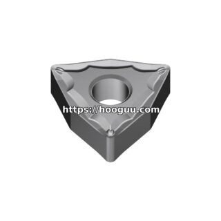
Korloy Chipbreaker Insert Example
Full insert designation: CNMG 120408-HM
- CNMG: Insert shape and style (C = 80° diamond, N = 0° clearance, M = tolerance class M, G = with chipbreaker hole)
- 12: Inscribed circle = 12.7 mm
- 04: Thickness = 4.76 mm
- 08: Corner radius = 0.8 mm
- HM: Chipbreaker code = Roughing (feed 0.20–0.45 mm/rev)
Need help matching a chipbreaker to your application? At hooguu.com, we stock the full Korloy chipbreaker range and can recommend the ideal geometry for your material, feed rate, and surface finish requirements. Contact our technical team for a free chipbreaker consultation.
Shop Related Products at HOOGUU