Copper C110 and Tellurium Copper C145: Tool Selection for High-Conductivity Alloys
Copper and copper alloys are among the most widely used materials in electrical, thermal management, and electronics applications. While pure copper (C110, ETP copper) offers the highest electrical and thermal conductivity, its extreme ductility and tendency to adhere to cutting tools make it one of the most challenging materials to machine. Tellurium copper (C145, CDA 145) was developed specifically to address this problem — the addition of tellurium creates a free-machining variant that retains excellent conductivity while dramatically improving chip breakability and surface finish. This guide covers the tooling strategies and cutting parameters for both alloys.
Material Properties Comparison
| Property | C110 (ETP Copper) | C145 (Tellurium Copper) |
|---|---|---|
| Hardness | 40-65 HV (soft annealed), 80-110 HV (half-hard) | 70-100 HV (as-drawn) |
| Tensile Strength | 200-250 MPa (annealed), 280-360 MPa (half-hard) | 280-380 MPa |
| Electrical Conductivity | 100% IACS (reference standard) | 90-93% IACS |
| Thermal Conductivity | 388 W/m·K | 350-370 W/m·K |
| Elongation at Break | 40-50% (annealed) | 15-25% |
| Tellurium Content | — | 0.4-0.7% |
| Chip Formation | Long, stringy, continuous | Short, segmented, easily broken |
| Machinability Rating | 20% (compared to free-machining brass) | 85-90% |
The machinability difference is dramatic. C110 is rated at just 20% relative machinability compared to C36000 free-machining brass, while C145 achieves 85-90%. This single property difference has massive implications for tool selection, cycle times, and production economics.
The Built-Up Edge Problem with C110
Pure copper’s extreme ductility causes material to weld onto the cutting edge during machining. This built-up edge (BUE) grows progressively, changing the effective cutting geometry, increasing cutting forces, and eventually breaking off — taking fragments of the carbide substrate with it. The result is poor surface finish, dimensional inaccuracy, and short tool life.
Key factors that exacerbate BUE in C110:
- Cutting speeds between 50-150 m/min (the “danger zone” for copper BUE)
- Rough or unpolished rake faces on the insert
- Negative or zero rake angles
- Insufficient coolant flow to the cutting zone
- Edge preparations that are too large (heavy honing)
Tool Selection for C110 (Pure Copper)
For C110, the insert or end mill must have an extremely sharp, polished cutting edge with a positive rake angle. Coating selection is critical — you need a coating that resists copper adhesion.
| Manufacturer | Grade / Tool Type | Key Feature | Application |
|---|---|---|---|
| Sandvik Coromant | H13A (uncoated carbide) / CD10 (PCD) | Ultra-fine grain, polished | Turning / high-volume production |
| Iscar | IC8 (uncoated carbide) / ID5 (PCD) | Sharp polished edge | Turning and grooving |
| Korloy | K10 / NC6110 | Fine-grain uncoated | General turning and finishing |
| Kennametal | K20 / KD140 (PCD) | Sub-micron grain, polished | Turning / high-speed finishing |
| OSG | HY-PRO Copper end mills | Polished flutes, sharp edge | Milling and slotting |
PCD (polycrystalline diamond) is the premium choice for C110. PCD inserts can maintain a mirror-finish cutting edge that virtually eliminates BUE formation. Cutting speeds of 300-800 m/min are achievable with PCD on pure copper, delivering exceptional surface finish and dimensional accuracy.
Tool Selection for C145 (Tellurium Copper)
C145 is much more forgiving. The tellurium inclusions act as chip breakers and provide a mild lubricating effect at the cutting interface. Standard carbide grades perform well, and PVD-coated grades with polished rake faces are often sufficient.
| Manufacturer | Grade | Coating | Application |
|---|---|---|---|
| Sandvik Coromant | 1025 / H13A | Uncoated | Turning and finishing |
| Iscar | IC8 / IC907 | Uncoated / PVD | General turning |
| Korloy | K10 / PC3625 | Uncoated / PVD TiAlN | Turning and milling |
| Kennametal | K20 / KC5025 | Uncoated / PVD | General purpose |
Cutting Parameters: Turning C110
| Operation | Tool Type | Cutting Speed (m/min) | Feed (mm/rev) | Depth of Cut (mm) | Coolant |
|---|---|---|---|---|---|
| Rough Turning (carbide) | Uncoated K10 | 150-250 | 0.15-0.30 | 1.5-3.0 | Flood emulsion or MQL |
| Finish Turning (carbide) | Uncoated K10 | 200-350 | 0.08-0.18 | 0.3-1.0 | Flood emulsion |
| Finish Turning (PCD) | PCD insert | 300-600 | 0.05-0.15 | 0.2-0.8 | MQL or flood |
| Grooving | Uncoated carbide | 100-200 | 0.06-0.12 | Groove width | Flood emulsion |
| Parting Off | Uncoated carbide | 80-150 | 0.05-0.10 | — | Flood emulsion |
Cutting Parameters: Turning C145
| Operation | Cutting Speed (m/min) | Feed (mm/rev) | Depth of Cut (mm) | Coolant |
|---|---|---|---|---|
| Rough Turning | 200-350 | 0.18-0.35 | 1.5-3.5 | Flood emulsion or MQL |
| Finish Turning | 300-500 | 0.08-0.20 | 0.3-1.0 | MQL or flood |
| Grooving | 150-280 | 0.08-0.15 | Groove width | Flood emulsion |
| Parting Off | 120-220 | 0.06-0.12 | — | Flood emulsion |
Milling Parameters
| Parameter | C110 (Pure Copper) | C145 (Tellurium Copper) |
|---|---|---|
| Cutting Speed | 150-300 m/min | 200-400 m/min |
| Feed per Tooth | 0.05-0.12 mm | 0.06-0.15 mm |
| Radial Depth | 50-70% of cutter Ø | 50-70% of cutter Ø |
| Axial Depth | 0.5-1.0 × Ø | 0.5-1.5 × Ø |
| Recommended Tool | 3-flute polished uncoated carbide | 3-4 flute polished carbide |
| Helix Angle | 35-45° high helix | 35-45° high helix |
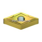
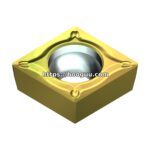
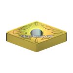
Insert Geometry for Copper Alloys
The geometry requirements for copper machining are the opposite of those for hardened steels:
- Rake angle: Highly positive (+5° to +15°) to produce a shear-cutting action that prevents material smearing
- Edge radius: Extremely sharp — maximum 5 μm edge radius for C110, up to 10 μm for C145
- Rake face: Mirror-polished to prevent copper adhesion
- Chipbreaker: Light-duty chipbreaker for C110 (long stringy chips need assistance breaking); standard chipbreaker for C145 (short chips are self-breaking)
- Clearance angle: 7-10° to prevent rubbing against the soft workpiece surface
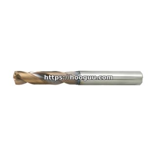
Drilling Copper Alloys
Drilling is particularly challenging in C110 due to the long, ductile chips that can wrap around the drill and damage the workpiece surface. Solutions include:
- Use split-point carbide drills with polished flutes
- Cutting speed: 80-180 m/min for C110, 120-250 m/min for C145
- Feed: 0.05-0.15 mm/rev depending on diameter
- Peck drilling (G83) with 1-2× diameter retracts to clear chips
- Through-coolant drills are strongly recommended for holes deeper than 3× diameter
Surface Finish Expectations
Copper components in electrical and thermal applications often require very fine surface finishes to maximize contact area and minimize electrical resistance at mating surfaces:
- C110 with PCD tools: Ra 0.2-0.4 μm achievable
- C110 with carbide tools: Ra 0.4-0.8 μm typical
- C145 with carbide tools: Ra 0.4-1.0 μm typical
- C145 with PCD tools: Ra 0.2-0.6 μm achievable
Summary
C110 pure copper demands ultra-sharp, polished-edge tools in uncoated carbide or PCD to manage its extreme ductility and built-up edge tendency. C145 tellurium copper is far more machinable, accepting standard carbide grades with minimal adhesion issues. For both alloys, positive rake geometry, high cutting speeds, and flood coolant are essential. When conductivity requirements allow, always specify C145 over C110 to reduce machining costs and improve productivity.
hooguu.com stocks polished-edge carbide inserts, PCD tools, and high-helix end mills optimized for copper and copper alloy machining. Whether you’re producing bus bars, heat sink components, or electrical contacts, our Korloy, Iscar, and Sandvik selections have the right tool for your high-conductivity application.
Shop Related Products at HOOGUU