High-Feed Milling vs Conventional Milling: MRR Comparison and Tool Selection
In rough milling operations, the race to maximize metal removal rate (MRR) often comes down to a fundamental choice: high-feed milling (HFM) or conventional milling. Each strategy takes a radically different approach to engaging the workpiece, and selecting the right one can mean the difference between a 15-minute cycle and a 45-minute cycle. This article breaks down the physics, economics, and practical applications of both strategies.
What Is High-Feed Milling?
High-feed milling uses a cutter with a very small lead angle (typically 10°–20°) or a curved cutting edge that directs cutting forces axially into the spindle rather than radially outward. This geometry allows extremely high feed rates—often 2–4× conventional values—while maintaining shallow axial depth of cut (ap = 0.5–2.0mm). The result is a thin, wide chip and a low cutting force per tooth.
The key insight is that cutting forces scale more aggressively with depth of cut than with feed rate. By keeping ap shallow and pushing feed rate high, HFM achieves superior MRR in many roughing scenarios while reducing spindle load.
Conventional Milling: The Baseline
Conventional milling—here referring to standard shoulder milling or face milling with 45° or 90° lead angle cutters—takes deeper axial cuts (ap = 3–8mm) at moderate feed rates (fz = 0.1–0.3 mm/tooth). It produces thicker chips and higher radial forces but is more versatile for finishing walls and achieving square shoulders.
MRR Comparison Table
| Parameter | High-Feed Milling | Conventional 45° Face Mill | Conventional 90° Shoulder Mill |
|---|---|---|---|
| Axial depth (ap) | 0.8–2.0 mm | 3–6 mm | 3–8 mm |
| Radial width (ae) | 60–80% D | 60–75% D | 30–50% D |
| Feed per tooth (fz) | 0.5–1.5 mm | 0.15–0.35 mm | 0.08–0.25 mm |
| Cutting speed (Vc) – Steel | 180–280 m/min | 150–250 m/min | 120–200 m/min |
| Table feed (Vf) example | 8,000–15,000 mm/min | 2,000–5,000 mm/min | 1,500–4,000 mm/min |
| MRR (cm³/min) – D50 cutter | 450–800 | 300–550 | 200–400 |
| Primary force direction | Axial (into spindle) | Mixed | Radial (outward) |
When High-Feed Milling Wins
High-feed milling dominates in these scenarios:
- Low-power machines: The axial force direction means less spindle deflection. A 15kW machine can run a D63 high-feed mill effectively where a conventional D63 face mill would overload.
- Long overhangs: When tool extension exceeds 3–4× diameter, radial forces cause chatter. HFM’s axial force profile keeps the cutter stable.
- Difficult-to-clamp workpieces: Thin-walled or flexible parts deflect under radial load. HFM pushes down rather than sideways.
- High-volume roughing: Open pockets, mold cavities, and die bases where the shallow ap can be compensated by multiple Z-level passes at very high feed rates.
When Conventional Milling Is Better
- Square shoulders: HFM leaves a scalloped floor and cannot produce a 90° wall. Conventional 90° end mills or shoulder mills are mandatory for vertical walls.
- Deep slotting: Narrow slots require full-depth engagement where HFM geometry is impractical.
- Low-volume, mixed-feature parts: When the same tool must rough, semi-finish, and finish, a conventional cutter offers more flexibility.
Real-World Example: Mold Base Roughing
A mold shop was roughing P20 steel mold bases (32 HRC) on a BT40 VMC with 18.5kW spindle. The existing process used a D50 conventional face mill at ap = 5mm, ae = 35mm, fz = 0.25mm/tooth, Vc = 180 m/min, producing an MRR of approximately 360 cm³/min. Each cavity required 45 minutes of roughing.
Switching to a D50 Korloy high-feed mill with 4 indexable inserts, the new parameters were: ap = 1.2mm, ae = 40mm, fz = 0.9mm/tooth, Vc = 220 m/min. The table feed jumped from 2,860 mm/min to 11,200 mm/min. With multiple Z-level passes at 1.2mm depth, the MRR reached 540 cm³/min—a 50% improvement. Roughing time dropped to 30 minutes per cavity.
The Korloy high-feed cutter’s curved-edge insert geometry produced smooth, axial-directed forces that the BT40 taper handled without fretting or pull-out. Tool life per set of inserts was 18 cavities vs. 12 with the conventional face mill.
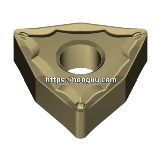
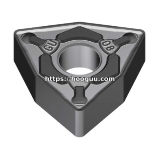
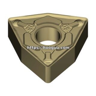
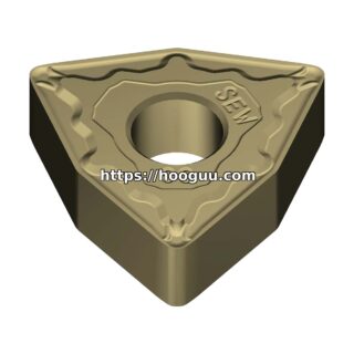
Insert and Tool Selection
For high-feed milling, insert selection focuses on:
- Insert shape: Trigon, round, or specially curved edge profiles that maintain a low effective lead angle across the depth of cut.
- Grade: PVD-coated grades with tough substrates (e.g., Korloy’s NC3020 or similar grades) handle the high-speed, light-cut conditions without micro-chipping.
- Number of flutes: More inserts mean higher table feed. A D63 cutter with 7 inserts at fz = 1.0mm and n = 1,500 RPM achieves Vf = 10,500 mm/min.
For conventional milling, tougher CVD-coated grades handle the deeper cuts and higher cutting forces. Korloy’s range of indexable milling cutters covers both strategies, making it easy to source compatible tooling from a single supplier through hooguu.com.
Combining Both Strategies
The most efficient roughing processes often combine both approaches. Use high-feed milling for the bulk material removal in open areas, then switch to a conventional shoulder mill for walls, corners, and features requiring square shoulders. Modern CAM systems can automatically transition between strategies based on the local geometry.
Conclusion
High-feed milling is not a replacement for conventional milling—it is a complementary strategy that excels in specific conditions. When the application calls for high MRR in open areas, especially on lower-power machines or with long tool extensions, HFM delivers measurable cycle time savings. Understanding where each strategy performs best allows process engineers to optimize roughing operations for both speed and cost. Explore the full range of Korloy high-feed and conventional milling cutters at hooguu.com to find the right tool for your next project.
Shop Related Products at HOOGUU