


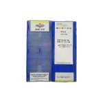
Why Insert Designations Matter More Than Catalog Pages
A turning insert part number such as CNMG 120408-PM 4325 already tells you the shape, the clearance angle, the tolerance class, the clamping style, the size, the thickness, the corner radius — and in the suffix, the chipbreaker and the grade. Reading that string correctly is the fastest way to find a drop-in replacement across brands, and the fastest way to avoid ordering an insert that will not clamp, will not fit the pocket, or will rub on a shoulder.
This reference walks through the ISO 1832 designation system letter by letter, gives the conversion between ISO metric and ANSI inch callouts, and provides cutting-parameter guidance by insert shape so the geometry choice is tied to real Vc, f and ap values.
The Anatomy of an ISO Insert Code
ISO 1832 defines a fixed eight-position structure. Only the first four characters are letters; the rest are numbers with a defined unit.
| Position | Meaning | Example (CNMG 120408) |
|---|---|---|
| 1 | Insert shape | C — 80° diamond |
| 2 | Clearance (relief) angle | N — 0° (negative, double-sided) |
| 3 | Tolerance class | M — molded, standard tolerance |
| 4 | Hole and chipbreaker configuration | G — hole, chipbreaker on one face |
| 5–6 | Cutting edge length / inscribed circle (mm) | 12 — 12.7 mm IC |
| 7–8 | Thickness (mm) | 04 — 4.76 mm |
| 9–10 | Corner radius (mm × 10) | 08 — 0.8 mm |
| Suffix | Chipbreaker and grade | -PM 4325 |
The suffix is not standardized — it belongs to the manufacturer. Sandvik uses two-letter chipbreaker codes (PM, MM, MR, QR), Iscar uses M3/M5, Seco uses M3/M5, Korloy uses HM/MA/SA, Tungaloy uses TM/GH. The grade (4325, IC8250, TP3501) always follows the chipbreaker.
Position 1: Insert Shape
The shape letter controls the trade-off between edge strength and accessibility. Included angle drives both: a larger included angle means more material behind the edge and better resistance to breakage, but less clearance to machine into a square shoulder or a profile.
| Letter | Shape | Included angle | Edge strength | Typical use |
|---|---|---|---|---|
| C | Diamond | 80° | High | General turning, facing, medium roughing |
| D | Diamond | 55° | Medium | Profiling, copy turning, shoulders |
| V | Diamond | 35° | Low | Fine profiling, tight contours, finishing |
| S | Square | 90° | Very high | Heavy roughing, interrupted cuts, 90° shoulders |
| T | Triangle | 60° | Medium-high | General turning, 3 usable corners, economical roughing |
| W | Trigon | 80° | High | Roughing with 6 corners, strong edge for forgings |
| R | Round | — | Highest | Heavy roughing, castings, scaly surfaces, radius blending |
| K | Diamond | 55° | Medium | Similar role to D, alternate tooling families |
Rule of thumb: as included angle falls, the maximum depth of cut the edge can survive falls with it, and the risk of chatter at the nose rises. A V insert that works well at ap 0.3 mm on a finishing pass will fail immediately at ap 3 mm on a casting skin.
Position 2: Clearance Angle
The second letter defines the angle between the flank and the vertical. It determines whether the insert is single-sided (positive) or double-sided (negative) and, therefore, whether the toolholder presents a negative or positive effective rake.
| Letter | Clearance | Insert type | Notes |
|---|---|---|---|
| N | 0° | Negative, double-sided | Most corners per insert, strongest edge, highest cutting forces |
| A | 0° | Negative, special | Restricted use, specific holders |
| B | 5° | Positive | Light-duty, small diameters |
| C | 7° | Positive | Most common positive clearance, single-sided |
| P | 11° | Positive | Free-cutting, low radial force, thin-wall parts |
| D | 15° | Positive | Very free-cutting, delicate edges |
An N insert is typically mounted in a holder that tilts it 5–7° so the effective rake becomes positive while the insert itself has two usable faces. That is why CNMG is described as a “negative” insert yet cuts with positive rake in a standard MCLNR holder.
Position 3: Tolerance Class
Tolerance class sets how tightly the inscribed circle and thickness are held. It matters most when indexing: a loose class can shift the cutting edge enough to change depth of cut on a multi-tooth setup, or to spoil a precision boring bar setting.
| Class | IC tolerance (mm) | Thickness tolerance (mm) | Typical application |
|---|---|---|---|
| G | ±0.025 | ±0.025 | Ground, precision turning and boring |
| M | ±0.08 to ±0.13 | ±0.13 | Molded, general turning (most common) |
| N | ±0.025 | ±0.025 | Ground to near-precision, finishing |
| U | ±0.13 to ±0.25 | ±0.13 | Molded, roughing only |
If a process repeats to ±0.02 mm on diameter without in-process gauging, a G-class insert is doing part of the work. In roughing, M or U class is sufficient and cheaper to run.
Position 4: Hole and Chipbreaker Configuration
This letter is the one most often misread when cross-referencing brands. It says whether the insert has a central clamping hole and how many faces carry a chipbreaker.
| Letter | Hole | Chipbreaker | Comment |
|---|---|---|---|
| A | Yes | None | Flat top, used for aluminum and finishing where a sharp edge is ground later |
| M | Yes | Both faces | Standard double-sided negative insert |
| G | Yes | One face | Single-sided chipbreaker on a double-sided body |
| N | No | None | Top clamp only, common on ceramic and CBN |
| R | No | One face | Top clamp, molded chipbreaker |
| T | Yes | One face, countersunk | Specific clamping systems |
An insert marked M will index to a fresh chipbreaker on the flip. An insert marked G will present a flat face when flipped and cannot be used for chip control — important when counting cost per edge.
Positions 5–10: Size, Thickness and Corner Radius
The numeric block is fully metric in ISO. Two digits for cutting edge length or IC in millimetres, two for thickness, two for corner radius in tenths of a millimetre.
| Code | Nominal IC / edge length | Code | Thickness | Code | Corner radius |
|---|---|---|---|---|---|
| 06 | 6.35 mm | 02 | 2.38 mm | 02 | 0.2 mm |
| 09 | 9.525 mm | 03 | 3.18 mm | 04 | 0.4 mm |
| 12 | 12.7 mm | 04 | 4.76 mm | 08 | 0.8 mm |
| 16 | 15.875 mm | 05 | 5.56 mm | 12 | 1.2 mm |
| 19 | 19.05 mm | 06 | 6.35 mm | 16 | 1.6 mm |
| 25 | 25.4 mm | 08 | 7.94 mm | 24 | 2.4 mm |
Converting ANSI to ISO
ANSI codes use inches in three positions: IC in eighths, thickness in sixteenths, radius in sixty-fourths.
| ANSI | IC | Thickness | Radius | ISO equivalent |
|---|---|---|---|---|
| CNMG-431 | 1/2 in (12.7 mm) | 3/16 in (4.76 mm) | 1/64 in (0.4 mm) | CNMG 120404 |
| CNMG-432 | 1/2 in | 3/16 in | 2/64 in (0.8 mm) | CNMG 120408 |
| CNMG-433 | 1/2 in | 3/16 in | 3/64 in (1.2 mm) | CNMG 120412 |
| WNMG-432 | 1/2 in | 3/16 in | 2/64 in | WNMG 080408 |
| TNMG-332 | 3/8 in (9.525 mm) | 3/16 in | 2/64 in | TNMG 160408 |
Note the W case: a trigon’s “size” in ISO is measured differently from its ANSI nominal, so always confirm the IC on the drawing rather than assuming a direct digit swap.
Corner Radius Selection Against Depth of Cut
The corner radius is the single most consequential number in the code for surface finish and chatter. Too small and the edge crumbles; too large and the tool rubs or chatters on light cuts.
| Radius | Max recommended ap | Typical feed | Application |
|---|---|---|---|
| 0.2 mm | 0.5 mm | 0.05–0.12 mm/rev | Finishing, small diameters, thin walls |
| 0.4 mm | 1.2 mm | 0.08–0.20 mm/rev | Light-medium turning, profiling |
| 0.8 mm | 2.5 mm | 0.15–0.35 mm/rev | General turning, the default choice |
| 1.2 mm | 4.0 mm | 0.25–0.50 mm/rev | Medium roughing, interrupted cuts |
| 1.6 mm | 6.0 mm | 0.30–0.60 mm/rev | Roughing, forged and cast surfaces |
A useful check is that feed should not fall below roughly 60% of the corner radius in mm per revolution, otherwise the chip thins under the nose and rubs instead of cutting.
Parameters by Insert Shape for Steel
Indicative starting values for medium-carbon steel at 180–220 HB, CVD grades, κr 90–95°. Adjust for machine rigidity and coolant.
| Shape | Vc (m/min) | f (mm/rev) | ap (mm) | Typical operation |
|---|---|---|---|---|
| C (80°) | 200–260 | 0.20–0.35 | 0.5–3.0 | General turning, facing |
| D (55°) | 200–250 | 0.15–0.30 | 0.5–2.0 | Profiling, shoulder work |
| V (35°) | 220–280 | 0.05–0.15 | 0.2–1.0 | Finishing, tight contours |
| S (90°) | 160–220 | 0.25–0.50 | 1.5–6.0 | Heavy roughing, interrupted |
| T (60°) | 190–250 | 0.20–0.40 | 1.0–4.0 | General roughing |
| W (80° trigon) | 180–240 | 0.25–0.45 | 1.5–5.0 | Roughing with 6 usable corners |
| R (round) | 150–210 | 0.30–0.60 | 2.0–8.0 | Scale and casting skin |
At the same Vc, moving from a T to a C insert typically allows one grade step harder because the 80° edge spreads load over a longer contact. Moving from C to V forces a tougher grade or a lower Vc to compensate for the fragile nose.
Chipbreaker Suffixes Across Brands
Because the suffix is proprietary, cross-referencing needs a table rather than a formula. The following shows the rough equivalence between common steel chipbreaker families.
| Sandvik | Iscar | Seco | Korloy | Tungaloy | Role |
|---|---|---|---|---|---|
| PR | F3P | F1 | FA | FS | Finishing, low feed |
| PM | M3P | M1 | SA | TM | Light-medium turning |
| MM | M5 | M3 | MA | GH | Medium turning, general purpose |
| MR | M5 | M5 | HM | GH | Medium roughing |
| QR | R3P | R1 | HA | RM | Roughing, high feed |
Treat this as a starting point, not a guarantee. Chipbreaker geometry differs in land width and groove depth even where the label matches, which changes the feed window by 10–20%.
Same Code, Different Grade: What Actually Changes
Two inserts can carry identical geometry codes and behave completely differently. The code says nothing about substrate cobalt content, coating architecture, or edge preparation.
- Substrate: a 10% Co fine-grain substrate tolerates interrupted cuts better than an 8% Co coarse-grain one at the same geometry.
- Coating: a 3 µm MT-TiCN + α-Al2O3 CVD stack runs hotter and faster than a 2 µm PVD TiAlN stack, but the PVD version holds a sharper edge for stainless and heat-resistant alloys.
- Edge prep: an ER-treated (rounded) edge resists breakage; a sharp ground edge cuts aluminium and finishes better.
When comparing a Sandvik 4325 against an Iscar IC8250 for the same CNMG 120408-MM application, compare coating thickness, edge hone and substrate grain size, not the letter string.
Checking a Substitution Before You Run It
- Match all four letters, or verify that the holder accepts the difference in clearance and clamping.
- Confirm IC and thickness against the drawing — a 120408 will not sit in a pocket cut for 09T304.
- Keep the corner radius within one step unless the finish requirement changes.
- Check the chipbreaker feed window against the planned f and ap.
- Reduce Vc by 10% on the first part until chip form is confirmed.
Get those five right and an insert code becomes a portable specification rather than a brand-locked part number.
Shop Related Products at HOOGUU