Machining 904L Stainless: High-Alloy Austenitic Tooling Requirements
904L (UNS N08904) is a super austenitic stainless steel containing 4.5% molybdenum, 23% nickel, and 20% chromium, delivering exceptional resistance to sulfuric acid, phosphoric acid, and chloride-containing environments. Originally developed by Outokumpu for the chemical process industry, 904L is also the case alloy used in Rolex watch cases and is specified for pharmaceutical and food processing equipment. Its high alloy content creates machining challenges that require dedicated tooling strategies beyond what standard 316L programs can deliver.
Material Properties
- Composition: 20% Cr, 23% Ni, 4.5% Mo, 1.5% Cu, 1% Mn, 0.02% C max
- Hardness: 150-190 HB (solution annealed)
- UTS: 500-700 MPa, yield strength: 220-310 MPa, elongation: 40-50%
- PREN: 36-40
- Machinability: 35-45% of B1112 (compared to 40-50% for 316L)
While 904L is softer than many high-strength alloys, its high nickel and molybdenum content creates specific challenges: aggressive work hardening, severe built-up edge formation, and long, unmanageable chips. The machinability gap between 904L and 316L is primarily driven by cutting forces (15-25% higher) and tool wear rates (30-50% faster).
Key Machining Challenges
- Built-up edge (BUE): The high nickel content (23%) increases chemical affinity between the workpiece and carbide insert coating. Material welds to the rake face at moderate speeds, eventually tearing away and taking coating with it. This is the dominant failure mechanism in 904L turning and milling.
- Work hardening: Surface hardness increases of 60-100 HB per pass are typical. Light cuts (ap below 0.3mm) penetrate only the hardened layer, accelerating tool wear exponentially.
- Chip management: Chips are extremely ductile and stringy. Without proper chipbreaker geometry, continuous chips wrap around the tool and workpiece, damaging surfaces and creating safety hazards.
- Low thermal conductivity: At approximately 12 W/m-K, 904L conducts heat away from the cutting zone less effectively than 304 (16 W/m-K) or 430 (25 W/m-K), concentrating thermal load on the insert.
Insert Grade Selection
Roughing:
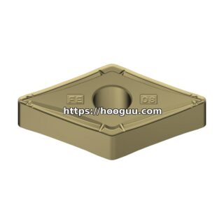
- Sandvik GC235 (CVD TiCN/Al2O3 triple-layer coating on tough substrate). CNMG 120412 with -MM chipbreaker optimized for austenitic stainless chip control.
- Kennametal KC5025 (PVD TiAlN, stainless-optimized). CNMG 120412 with -RP chipbreaker.
- Iscar SUMO TEC IC908 (PVD TiAlN with SumoTec post-coating treatment for edge toughness).
Semi-Finishing:
- Sandvik GC225 (CVD, wear-resistant). CNMG 120408 with wiper flat for improved surface finish.
- Seco TP2501 (CVD Duratomic). Excellent balance of wear resistance and toughness.
Finishing:
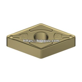
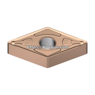
- Sandvik GC215 (PVD micro-grain carbide). DNMG 150404 with polished rake face. The PVD coating provides a sharper cutting edge that reduces BUE compared to CVD in finishing applications.
- Mitsubishi VP15TF (PVD Miracle sigma coating). Proven performer on austenitic stainless finishing.
- Tungaloy NS9530 (nano-TiAlN). For mirror finish requirements below Ra 0.4 micrometers.
Grooving and Parting:
- Sandvik GC1125 N-style grooving blades with -RM chipbreaker, 3-4mm width
- Kennametal KC5010 for parting operations up to 65mm bar diameter
Cutting Parameters
Turning – 904L (Solution Annealed):
- Vc: 80-140 m/min (CVD roughing), 120-200 m/min (PVD finishing)
- fn: 0.18-0.32 mm/rev roughing, 0.08-0.18 mm/rev finishing
- ap: 2.0-5.0 mm roughing, 0.3-1.0 mm finishing
- Coolant: Flood emulsion at 8-10%, 40-70 bar pressure. Direct nozzle at both rake face and flank.
- Tool life: 30-65 minutes per edge at 110 m/min (CVD roughing)
Key rule: Maintain cutting speed above 80 m/min to avoid the BUE formation zone (40-80 m/min). Below 80 m/min, nickel transfer to the insert accelerates dramatically.
Milling 904L
- 4-5 flute solid carbide end mills, AlTiN or AlCrN coating, 12-25mm diameter
- Vc: 60-120 m/min (stay above BUE zone)
- fz: 0.05-0.10 mm/tooth
- Radial engagement: 50-70% diameter (peripheral), 5-8% (trochoidal slotting)
- Axial depth: 0.8-1.5 x diameter
- Use climb milling exclusively. Conventional milling increases work hardening and accelerates flank wear.
- Indexable face milling: Round insert cutters (RCMT 1204) with Sandvik GC225 at Vc 100-150 m/min, fz 0.15-0.25 mm/tooth
Drilling and Tapping
Drilling:
- Solid carbide, 135 deg split point, TiAlN coating, through-tool coolant
- Vc: 40-80 m/min, fn: 0.06-0.12 mm/rev (8-12mm drills)
- Peck depth: 2.0-3.0 x diameter with full retract
- Coolant: 40-60 bar through tool
- Expected life: 100-250 holes per drill (10mm x 30mm deep)
Tapping:
- Spiral-flute HSS-E (cobalt) taps with TiN or TiCN coating
- Speed: 5-12 m/min with peck tapping cycle
- Form (roll) tapping preferred: produces 25-30% stronger threads and eliminates chip evacuation issues
- Use form taps with TiCN coating and interrupted thread geometry for reduced torque
Watch Case and Precision Component Machining
904L’s association with luxury watch manufacturing creates specific process requirements:
- Multi-axis milling: Watch case profiles require 4-5 axis simultaneous milling with ball-nose end mills. Use 2-6mm diameter solid carbide ball-nose cutters with AlTiN-Si coating at Vc 80-120 m/min and fz 0.01-0.03 mm/tooth.
- Surface finish: Satin finish surfaces (Ra 0.2-0.4 micrometers) are achieved through finish milling followed by manual polishing. Target Ra below 0.6 micrometers from the CNC operation to minimize hand-finishing time.
- Burr control: 904L burrs are tough and work-hardened. Use dedicated deburring tools (single-flute carbide burr cutters) immediately after each operation. Do not allow burrs to age-harden between operations.
- Cleanliness: For watch and pharmaceutical applications, use vegetable-oil-based MQL or synthetic coolant to avoid mineral oil contamination that complicates subsequent PVD coating or electropolishing operations.
Chemical Process Equipment Fabrication
Large 904L components for chemical plants (heat exchanger tubesheets, reactor internals, agitator shafts) require different approaches:
- Use heavy-duty turning centers with 30+ kW spindle power for large-diameter roughing
- Program constant surface speed (CSS) and avoid dwell at any position on the workpiece
- For tubesheet drilling (hundreds of holes), use indexable insert drills (Sandvik CoroDrill 880 or Kennametal KSEM) rather than solid carbide for economic efficiency on deep hole patterns
- Budget 2-3x the machining time of equivalent 316L components and 1.5-2x the tooling cost
Summary
904L machining success depends on three factors: selecting stainless-optimized insert grades (CVD for roughing, PVD for finishing), maintaining cutting speeds above the BUE zone (80+ m/min), and using aggressive chipbreaker geometries to manage the alloy’s ductile chips. With proper tooling and parameters, 904L can be machined productively despite its high alloy content and challenging chip behavior.
Shop Related Products at HOOGUU