Machining Nitronic 60: Galling-Resistant Stainless Tooling Strategy
Nitronic 60 (UNS S21800, Armco 21-6-9) is a nitrogen-strengthened austenitic stainless steel engineered for exceptional galling resistance, high-temperature strength, and cavitation erosion resistance. Specified for valve stems, pump shafts, marine fasteners, and cryogenic fittings, Nitronic 60 presents unique machining challenges that distinguish it from standard 300-series austenitic stainless steels. Its high nitrogen content (0.20-0.35%) and manganese (8-10%) create a tough, work-hardening matrix that demands specific insert grades and aggressive cutting parameters to avoid premature tool failure.
Material Properties
- Composition: 17% Cr, 8.5% Ni, 8.5% Mn, 4% Si, 0.25% N
- Hardness: 180-220 HB (annealed), up to 350+ HB after severe cold work
- Ultimate tensile strength: 690-830 MPa (annealed), 1000+ MPa (cold worked)
- Elongation: 50-60% (annealed)
- Machinability rating: 30-40% of B1112 (compared to 40-50% for 304 and 316)
Nitronic 60 is approximately 30% more difficult to machine than 316L due to its higher manganese and nitrogen content, which increase work-hardening rate and cutting forces. However, it machines more easily than 17-4 PH H900 or superalloy grades.
Why Nitronic 60 Is Difficult
- High work-hardening rate: The nitrogen in solid solution dramatically increases the stacking fault energy response, causing rapid strain hardening at the cutting edge. Surface hardness can increase 100-150 HB in a single pass.
- Galling tendency: The same galling resistance that makes Nitronic 60 valuable in service also causes material transfer (built-up edge) on the insert rake face, particularly with uncoated or polished carbide.
- Long, tough chips: High ductility and toughness produce stringy, continuous chips that wrap around the workpiece and tool holder, creating safety hazards and surface finish damage.
- Low thermal conductivity: At approximately 13 W/m-K, heat concentrates at the cutting zone more than in ferritic or martensitic stainless grades.
Insert Grade Selection
Roughing:
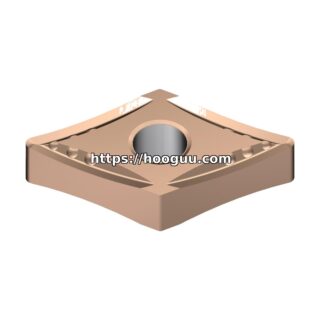
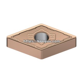
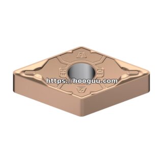
- Sandvik GC235 (CVD TiCN/Al2O3, tough substrate designed for stainless steel). CNMG 120412 with -MM chipbreaker geometry specifically designed for stainless chip control.
- Kennametal KC5025 (PVD TiAlN, medium-tough substrate). CNMG 120412 with -RP chipbreaker.
- Iscar SUMO TEC IC908 (PVD TiAlN with SumoTec post-treatment for edge toughness).
Semi-Finishing:
- Sandvik GC225 (CVD, wear-resistant grade for stainless). CNMG 120408 with wiper flat.
- Mitsubishi MC7025 (CVD, stainless-optimized coating).
Finishing:
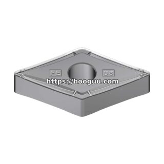
- Sandvik GC215 (PVD-coated micro-grain carbide) or Tungaloy NS9530 (nano-TiAlN for mirror finish). DNMG 150404 with polished rake face and sharp edge (0.01mm hone).
- Seco CP100 (uncoated fine-grain carbide) for ultra-fine finishing where coating adhesion issues arise.
Key insert selection principle: Use CVD-coated inserts for roughing (better crater wear resistance against work-hardened chips) and PVD-coated inserts for finishing (sharper edge, less BUE tendency). Avoid uncoated carbide except for specialized finishing operations.
Cutting Parameters
Turning – Annealed Nitronic 60:
- Vc: 80-140 m/min (CVD carbide roughing), 120-200 m/min (PVD finishing)
- fn: 0.18-0.30 mm/rev roughing, 0.08-0.18 mm/rev finishing
- ap: 2.0-5.0 mm roughing, 0.3-1.0 mm finishing
- Coolant: Flood emulsion at 8-10% concentration, 40-70 bar pressure
- Tool life: 30-60 minutes per edge at 100 m/min roughing
Critical rule: Never take cuts below 0.3mm depth on Nitronic 60. The work-hardened layer from the previous pass is typically 0.2-0.3mm thick. Cutting within this layer causes rapid tool wear and poor surface finish. Always ensure the insert penetrates below the hardened surface.
Chip Control Strategy
Chip management is the single biggest operational challenge with Nitronic 60. Recommended approaches:
- Use stainless-specific chipbreakers: Sandvik -MM (medium machining) or -MF (medium finishing) geometries are designed to curl and break austenitic stainless chips. Kennametal -RP geometry is similarly optimized.
- Increase feed rate: Higher feed rates produce thicker chips that break more readily. Running fn above 0.20 mm/rev significantly improves chip breakage versus light feeds.
- Program chip-breaking retractions: In CNC programs, insert brief retract moves (0.5mm retract, no feed) every 3-5 revolutions to snap chips.
- High-pressure coolant: Directing 70+ bar coolant at the chip curl zone helps fracture continuous chips. Some shops use targeted air blast nozzles alongside flood coolant for additional chip breaking force.
Milling Nitronic 60
- 4-5 flute solid carbide end mills, AlTiN or AlCrN coating, 12-25mm diameter
- Vc: 60-120 m/min
- fz: 0.05-0.10 mm/tooth
- Radial engagement: 50-70% of diameter for peripheral milling, 5-8% for trochoidal slotting
- Axial depth: 0.8-1.5 x diameter
- Use climb milling exclusively. Conventional milling increases work hardening and accelerates flank wear.
Drilling and Tapping
Drilling:
- Solid carbide, 135 deg split point, TiAlN coating, through-tool coolant
- Vc: 40-80 m/min, fn: 0.06-0.12 mm/rev (6-12mm drills)
- Peck depth: 2.0-3.0 x diameter with full retract
- Coolant pressure: 40-60 bar through tool
- Expected life: 80-200 holes per drill (10mm x 30mm deep)
Tapping:
- Spiral-flute HSS-E (cobalt) taps with TiN or TiCN coating
- Speed: 5-12 m/min
- Use form (roll) taps where possible. Thread forming produces 30% stronger threads in Nitronic 60 and eliminates chip evacuation problems in blind holes.
- For cut tapping, use peck tapping cycles with 3-5mm peck depth and full retract for chip clearance.
Surface Finish and Integrity
Nitronic 60’s galling resistance and low thermal conductivity can produce surface tears and smeared metal if inserts are worn. Target specifications:
- Rough turned: Ra 1.6-3.2 micrometers (acceptable for non-bearing surfaces)
- Finish turned: Ra 0.4-1.0 micrometers with fresh PVD inserts and fn below 0.12 mm/rev
- Change inserts at VB 0.2mm maximum. Beyond this, surface tearing becomes visible and may require grinding to correct.
Valve Stem and Shaft Applications
Nitronic 60 is commonly specified for valve stems, where the combination of corrosion resistance, galling resistance, and moderate strength is ideal. Process recommendations for shaft turning:
- Use steady rest support for shafts exceeding 8:1 length-to-diameter ratio to prevent chatter.
- Turn the OD in a single continuous pass where possible to avoid dwell marks that create visible surface lines.
- For sealing surfaces, target Ra 0.4-0.8 micrometers. Consider diamond burnishing as a final operation to achieve Ra below 0.2 micrometers without grinding.
- Thread relief grooves should be cut with a positive-rake grooving insert (N-style, 3mm width) at fn 0.05-0.08 mm/rev to prevent burr formation.
- Deburr all edges immediately after machining. Nitronic 60 burrs work-harden rapidly and become nearly impossible to remove after aging in the work environment.
Shop Related Products at HOOGUU