Understanding Molybdenum TZM: Properties and Machining Challenges
Molybdenum TZM (Titanium-Zirconium-Molybdenum) is a high-performance refractory alloy composed of approximately 99.4% molybdenum, 0.5% titanium, 0.08% zirconium, and trace carbon. Developed for applications requiring exceptional strength at elevated temperatures, TZM maintains mechanical integrity above 1,200°C — far exceeding the capabilities of conventional steels and nickel-based superalloys. Common applications include furnace components, rocket nozzles, hot-work die inserts, semiconductor processing fixtures, and aerospace structural members.
The alloy’s extreme hardness (250–320 HV in stress-relieved condition), low thermal expansion coefficient (4.9 × 10⁻⁶/°C), and high thermal conductivity (119 W/m·K) make it both valuable and notoriously difficult to machine. Tool wear rates can be 10–20 times higher than when machining hardened steels, demanding careful selection of cutting tool materials, geometries, and parameters.
Recommended Cutting Tool Materials for TZM
Carbide Grades (Primary Choice)
Uncoated fine-grain and ultra-fine-grain tungsten carbide inserts remain the workhorse for TZM machining. The preferred grades fall in the ISO P10–P20 range (ANSI C2–C5), featuring grain sizes of 0.4–0.8 μm with cobalt binder content of 6–8%. Key carbide insert selections include:
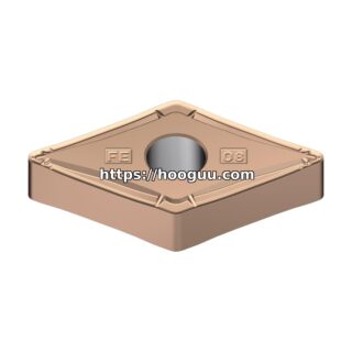
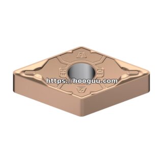
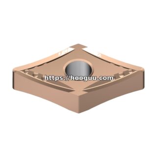
- Turning (roughing): C5/ISO P15 carbide, 15–25° rake angle, 5–8° clearance, chip breaker geometry. Recommended inserts: CNMG 120408, WNMG 080408, DNMG 150408.
- Turning (finishing): C2/ISO P10 carbide, sharp uncoated edge, 20–30° rake angle. Recommended: CCMT 09T304, DCMT 070202.
- Milling: C3–C5 grade, positive-rake geometry with reinforced edge. Recommended: APMT 1135, SEKN 1203AFTN.
- Drilling: Solid carbide or carbide-tipped, 118–135° point angle, 8–12° helix angle.
Coated Carbide (Limited Applications)
TiAlN-coated carbide can extend tool life by 20–40% in specific finishing operations where cutting temperatures stay below 800°C. However, coating adhesion failure is common in heavy cuts due to TZM’s abrasive nature. AlCrN coatings perform marginally better at elevated temperatures but are still secondary to uncoated fine-grain grades.
CBN (Cubic Boron Nitride)
CBN inserts (ISO BZN grade) offer superior wear resistance for finish turning of TZM at higher speeds. They are best suited for light interrupted cuts and continuous finishing passes where the workpiece hardness exceeds 280 HV.
Cutting Parameters: Turning TZM
| Operation | Speed (SFM) | Speed (m/min) | Feed (IPR) | Feed (mm/rev) | Depth of Cut (in) | Depth of Cut (mm) |
|---|---|---|---|---|---|---|
| Rough Turning | 80–120 | 25–37 | 0.006–0.010 | 0.15–0.25 | 0.040–0.080 | 1.0–2.0 |
| Semi-Finish | 120–180 | 37–55 | 0.004–0.007 | 0.10–0.18 | 0.020–0.040 | 0.5–1.0 |
| Finish Turning | 180–250 | 55–76 | 0.002–0.004 | 0.05–0.10 | 0.005–0.020 | 0.13–0.50 |
Tool life targets for roughing: 15–30 minutes per edge. Finishing: 45–90 minutes per edge. Expect flank wear land (VB) of 0.3–0.5 mm at end of useful life.
Cutting Parameters: Milling TZM
| Operation | Speed (SFM) | Feed/Tooth (IPT) | Feed/Tooth (mm) | Axial DOC (in) | Radial DOC (in) |
|---|---|---|---|---|---|
| Face Milling (rough) | 80–120 | 0.004–0.007 | 0.10–0.18 | 0.060–0.120 | 60–80% of diameter |
| Face Milling (finish) | 150–220 | 0.003–0.005 | 0.08–0.13 | 0.010–0.030 | 40–60% of diameter |
| Slot Milling | 60–90 | 0.002–0.004 | 0.05–0.10 | 0.5× diameter | Full width |
| End Milling (profile) | 100–150 | 0.003–0.005 | 0.08–0.13 | 1.0–1.5× diameter | 5–15% of diameter |
Use climb milling direction to reduce tool entry shock. Minimum 4-flute carbide end mills, 1/2″ to 3/4″ diameter recommended. Smaller diameters risk chipping at the cutting edge.
Cutting Parameters: Drilling and Tapping TZM
| Operation | Speed (SFM) | Feed (IPR) | Notes |
|---|---|---|---|
| Drilling (≤ 1/4″ dia) | 40–60 | 0.001–0.002 | Peck cycle, 3× diameter peck depth |
| Drilling (1/4″ – 1/2″) | 50–80 | 0.002–0.004 | Peck cycle, 2× diameter peck depth |
| Drilling (> 1/2″) | 60–90 | 0.004–0.006 | Pilot drill recommended, then step drill |
| Tapping | 10–15 SFM | — | Spiral-point, H3 limit, TiN coated HSS |
Coolant Strategy
Flood coolant is mandatory for TZM machining. Water-soluble semi-synthetic or synthetic coolants at 8–10% concentration provide the best combination of lubrication and heat extraction. Minimum flow rate: 3–5 GPM directed at the cutting zone. For deep-hole drilling, through-tool coolant at 150–250 PSI is strongly recommended. High-pressure coolant (1,000–3,000 PSI) significantly improves chip evacuation and extends tool life by 30–50% during turning operations.
Never machine TZM dry. Dry cutting causes rapid thermal cracking of carbide edges and workpiece surface burning. Minimum quantity lubrication (MQL) is marginally acceptable only for very light finishing passes.
Tool Geometry Best Practices
Edge preparation is critical. A light hone of 0.0005–0.001″ (13–25 μm) on the cutting edge prevents micro-chipping during entry into the hard TZM surface. For finishing, a T-land or chamfer of 0.002–0.004″ at 20–25° reinforces the edge while maintaining a free-cutting geometry. Rake angles between 15–25° positive balance cutting forces against edge strength. Nose radii of 0.015–0.031″ (0.4–0.8 mm) are standard for turning; larger radii improve surface finish but increase radial cutting forces.
Workholding and Setup Considerations
TZM’s high density (10.2 g/cm³) means workpieces are heavy — a 6″ diameter × 12″ bar weighs approximately 70 lbs. Rigid setups with minimal overhang are essential. Collet chucks or precision 3-jaw chucks with full-grip jaws provide the best concentricity. For milling, use mechanical clamps rather than magnetic chucks (TZM is non-magnetic). Vibration-damping boring bars with tungsten or carbide shanks minimize chatter during internal turning operations.
Surface Finish Expectations
As-machined TZM surfaces typically achieve 32–63 μin Ra (0.8–1.6 μm) with proper finishing parameters. Grinding with diamond or CBN wheels can achieve 8–16 μin Ra (0.2–0.4 μm). For optical or semiconductor applications requiring mirror finishes, lapping with 3–6 μm diamond paste produces surfaces below 4 μin Ra (0.1 μm). Post-machining electropolishing in a sulfuric-methanol bath can further reduce surface roughness by 50–70%.
Safety Considerations
TZM machining produces fine metallic dust and sharp, needle-like chips. Adequate chip guarding, dust extraction at the source, and proper PPE (safety glasses, gloves, respiratory protection during blow-off) are required. Molybdenum dust is classified as a nuisance dust with a TWA exposure limit of 10 mg/m³. Coolant mist collectors are recommended for operations using flood coolant at high pressure.
Summary
Machining TZM demands respect for the material’s extreme hardness and abrasiveness. Uncoated fine-grain carbide in the C2–C5 range, conservative cutting speeds of 80–250 SFM, generous flood coolant, and proper edge preparation form the foundation of successful TZM machining. By following these parameters and guidelines, shops can achieve acceptable tool life, dimensional accuracy, and surface finish when working with this demanding refractory alloy.
Shop Related Products at HOOGUU