
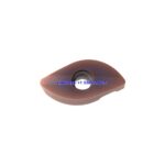
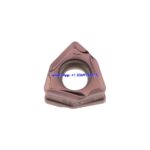
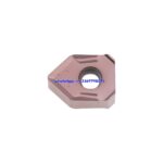
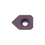
Why Parting Off Is the Most Demanding Turning Operation
Parting off — cut-off turning — looks simple on a process sheet: one radial plunge, one finished part. In practice it is the operation that breaks the most inserts, produces the most chatter, and generates the highest scrap rate on any lathe. The reason is geometric. A parting tool works with a very narrow insert buried deep in a slot, so the tool has almost no room to deflect chips, coolant has almost no room to reach the cutting edge, and the effective stiffness of the tool drops as the blade goes deeper. Every parameter that would be forgiving in longitudinal turning becomes critical in parting.
This guide explains how to select a parting and grooving system in a disciplined way: first the insert width, then the chip former geometry, then the grade, then the cutting parameters. It compares how Sandvik Coromant, Iscar, Walter and TaeguTec approach the same problem, and it gives parameter tables that can be used as a starting point for steel, stainless steel, cast iron, aluminium and heat-resistant alloys.
Step 1: Select the Insert Width Before Anything Else
Insert width determines three things at once: the material lost per part (kerf), the stiffness of the blade, and the chip thickness the chip former can tolerate. The rule of thumb in production is simple — choose the narrowest insert that survives the depth of cut, then move up one size if chatter or insert breakage appears.
A narrow insert removes less material and needs less spindle power, but it deflects more and its chip former has less room. A wide insert is stable and tolerates higher feed, but it wastes bar stock and can overload small lathes. On a bar-fed machine producing millions of parts, a 0.5 mm reduction in kerf is often worth more than any other process improvement.
Recommended Width, Feed and Capacity by Insert Size
| Insert width | Typical feed (mm/rev) | Max parting depth (radial) | Practical bar diameter | Typical use |
|---|---|---|---|---|
| 1.5 – 2.0 mm | 0.05 – 0.10 | 3 – 6 mm | up to Ø13 mm | Small precision parts, brass and aluminium, watch and medical components |
| 2.5 mm | 0.08 – 0.12 | 5 – 8 mm | Ø13 – Ø20 mm | General small-part turning, tube and thin-wall work |
| 3.0 mm | 0.10 – 0.15 | 8 – 12 mm | Ø20 – Ø35 mm | The most common general-purpose size on CNC lathes |
| 4.0 mm | 0.12 – 0.18 | 12 – 18 mm | Ø30 – Ø55 mm | Medium bar work, grooving with wide shoulders |
| 5.0 – 6.0 mm | 0.16 – 0.25 | 20 – 30 mm | Ø50 – Ø90 mm | Heavy shafts, interrupted cuts, forged blanks |
These values assume a rigid, correctly centred tool on a machine with good coolant pressure. If the blade overhangs more than roughly 1.5 times its height, or if the part is supported only by the chuck, reduce the feed by 20–30% and expect to use a lighter chip former.
Step 2: Match the Chip Former Geometry to the Application
Parting insert geometries fall into three families, and mixing them up is the single most common cause of poor chip control.
- Flat-top / neutral geometry. No chip former, or a very shallow one. Used for grooving where the insert cuts on the side, for form grooving, and for materials that produce naturally short chips (cast iron, brass, some plastics). It is also the correct choice for blind grooves and shoulders where a curved former would rub.
- Standard parting former. A narrow, usually symmetric groove behind the cutting edge that rolls the chip into a tight coil. This is the default for steel and stainless steel at moderate feeds.
- High-feed / reinforced former. Wider and stronger, with a land that supports the edge under higher feed rates. Used on large diameters, on tough materials, and on machines with enough power to push 0.15 mm/rev or more.
A useful check: if chips come out as long ribbons, the former is too open for the feed, or the feed is too low for that former. If the insert breaks at the corner, the former is too aggressive for the material or the tool is not on centre.
Chip Former Selection Matrix
| Application | Geometry family | Reason |
|---|---|---|
| Cut-off, ISO P steel, Ø20–Ø45 | Standard parting former | Reliable coil formation at 0.10–0.15 mm/rev |
| Cut-off, ISO M stainless | Standard former with sharp edge / polished rake face | Reduces work hardening and built-up edge |
| Cut-off, ISO K cast iron | Flat or shallow former | Dust-like chips need no guidance; a former only adds friction |
| Cut-off, ISO N aluminium | Polished flat or shallow former with high rake | Prevents built-up edge and smearing on the groove walls |
| Side grooving / shoulder grooving | Neutral, multi-tooth or full-radius | Allows radial and axial relief without rubbing |
| Face grooving | Curved (radius-matched) insert | Curvature must match groove radius to avoid heel rub |
| Interrupted cut / forged skin | Reinforced former, edge chamfer | Survives impact at entry; chamfer protects the corner |
Step 3: Grade Selection for Parting and Grooving
Parting grades are usually tougher and less wear-resistant than turning grades, because the insert is thin, the edge is unsupported and any micro-chipping quickly becomes a break. PVD TiAlN and TiCN coatings dominate here, since they can be applied thin and keep a sharp, tough edge. CVD-coated grades appear where abrasive materials or high speeds demand more wear resistance.
Typical grade behaviour in the main material groups:
| ISO group | Material | Vc (m/min) | Feed (mm/rev, 3 mm width) | Grade character |
|---|---|---|---|---|
| P | Carbon and alloy steel, 180–300 HB | 90 – 150 | 0.10 – 0.15 | PVD TiAlN, tough substrate; CVD TiCN for higher speed |
| P (hard) | Steel 300–400 HB, forged skin | 60 – 100 | 0.08 – 0.12 | Extra-tough, thicker coating, reinforced edge |
| M | Austenitic stainless 304/316, duplex | 50 – 90 | 0.08 – 0.12 | Sharp edge, polished rake, PVD TiAlN; avoid rubbing |
| K | Grey and nodular cast iron | 100 – 180 | 0.10 – 0.16 | Thin CVD or uncoated; abrasion resistance matters |
| N | Aluminium, copper, brass | 200 – 500 | 0.10 – 0.20 | Uncoated or DLC, high positive rake, polished |
| S | Inconel, titanium, cobalt alloys | 30 – 60 | 0.06 – 0.10 | Sharp, tough PVD grade; low speed, generous coolant |
| H | Hardened steel 45–60 HRC | 50 – 90 | 0.06 – 0.10 | CBN or ceramic for volume work; carbide only for short runs |
In mixed production, one tough PVD TiAlN universal insert covers P, M and S reasonably well; dedicated grades pay back once a single material family dominates the workload.
Step 4: How the Major Brands Structure Their Parting Systems
The four systems most often specified in Asian and European job shops solve the same problem with different mechanical priorities: insert clamping, blade rigidity, and how quickly the insert can be changed.
Sandvik Coromant CoroCut 1-2
CoroCut 1-2 uses a rail-based clamping system with a spring-loaded blade and inserts that seat on a dovetail rail. The design is aimed at minimum blade height and maximum depth capability for a given width, which suits sliding-head and small CNC lathes where space is tight. The insert range covers 1.0 mm to 6.0 mm widths with matched chip formers, and grade coverage is extensive: GC1125 and GC1135 for ISO P, GC2330 for ISO M, and uncoated or thin-coated options for N. CoroCut also provides radius-matched inserts for face grooving and internal grooving, so one blade family covers a large part of the work envelope.
Iscar Tang-Grip and Grip Systems
Iscar’s parting line is built around a rigid, self-clamping blade with a dovetail or wedge clamp that pulls the insert into a V-seat. This gives very high repeatability of index position, which matters when a groove width is held to a few hundredths of a millimetre. Iscar’s standard parting inserts are offered in PVD TiAlN grades (IC908 family) and tougher coated grades for interrupted cuts (IC808/IC328 families), plus polished uncoated inserts for aluminium. The Tang-Grip family extends the concept to tangential grooving and multi-directional turning, which is useful where a groove also needs a chamfer or a radius in the same set-up.
Walter Cut SX and GX
Walter’s parting system uses a screwed or clamped insert on a hardened blade with a strong self-locating seat. Walter positions its parting grades around PVD-coated WPP-type inserts for steel and stainless, and tough uncoated or thin-coated inserts for cast iron and aluminium. The distinguishing feature is the SX self-clamping geometry, which allows insert change without removing the blade, and a family of inserts with reinforced corners for interrupted cuts on forged and cast blanks.
TaeguTec T-Clamp
TaeguTec’s parting and grooving range uses a top-clamp design with a hardened blade and a broad insert programme, including full-radius and multi-tooth forms. Grades such as TT9080 (PVD) and TT8020/TT9030 (CVD) cover P, M and K, and the line includes dedicated inserts for tube parting and for grooving close to a shoulder. The practical advantage is a large catalogue of standard widths, which reduces the need for special tooling on mixed job-shop work.
System Comparison
| Feature | Sandvik CoroCut 1-2 | Iscar Tang-Grip / Grip | Walter Cut SX | TaeguTec T-Clamp |
|---|---|---|---|---|
| Clamping principle | Rail / spring blade, dovetail seat | Wedge or dovetail self-clamp into V-seat | Screw or self-clamping seat | Top clamp on hardened blade |
| Width range | 1.0 – 6.0 mm | 1.5 – 8.0 mm | 2.0 – 8.0 mm | 1.5 – 8.0 mm |
| Strength | Deepest reach for blade height; wide grooving programme | Index repeatability; tangential and multi-directional options | Fast insert change; reinforced corners | Broad standard catalogue; cost-effective coverage |
| Best fit | Small lathes, sliding-head, deep parting | High-volume close-tolerance grooves | Job shops with mixed and interrupted cuts | General job-shop and production turning |
Step 5: Cutting Parameters and Practical Settings
Parting parameters are lower than turning parameters for the same material, mainly because chip evacuation is poor and the tool is slender. The table below gives starting values for a 3 mm wide PVD-coated carbide insert on a rigid CNC lathe with through-tool coolant.
| Material | Vc (m/min) | Feed (mm/rev) | Coolant | Notes |
|---|---|---|---|---|
| Low-carbon steel 1020 | 120 – 160 | 0.12 – 0.16 | Flood, 8–15 bar | Highest speeds in the P group |
| Alloy steel 4140 (28 HRC) | 90 – 130 | 0.10 – 0.14 | Flood | Reduce 20% if skin or scale present |
| Stainless 304 | 55 – 80 | 0.08 – 0.12 | High-pressure flood | Never dwell; keep feed constant to avoid work hardening |
| Stainless 316 | 50 – 70 | 0.08 – 0.11 | High-pressure flood | Sharp edge, polished rake essential |
| Grey cast iron 200 HB | 120 – 180 | 0.10 – 0.16 | Flood or MQL | Dry running acceptable on some machines |
| Aluminium 6061 | 250 – 450 | 0.12 – 0.20 | Flood or MQL | Polished uncoated insert; watch built-up edge |
| Titanium Ti-6Al-4V | 30 – 45 | 0.06 – 0.09 | High-pressure flood, never dry | Keep tool engaged; avoid re-entry |
| Inconel 718 | 25 – 40 | 0.05 – 0.08 | High-pressure flood | Expect short tool life; consider peck parting |
| Hardened steel 50 HRC | 50 – 70 | 0.06 – 0.10 | Flood | Use CBN above roughly 1000 parts |
Three settings matter more than any parameter table:
- Centre height. On-centre is mandatory. Above centre the insert rubs on the heel and the part gets a pip; below centre the insert is pulled into the work and can break. Align within 0.05 mm of centre.
- Overhang. Keep the blade as short as the depth allows. A 3 mm insert on a blade protruding 25 mm will chatter where the same insert at 15 mm cuts cleanly.
- Coolant direction. Aim the stream at the flank, not the top face, and use the highest pressure available. In deep parting, through-blade coolant ports are more effective than external nozzles.
Troubleshooting: What the Symptom Tells You
| Symptom | Likely cause | Corrective action |
|---|---|---|
| Long ribbon chips wrapping the blade | Feed too low for the chip former, or former too open | Increase feed in 0.02 mm/rev steps; change to a tighter former |
| Chatter and a stepped groove wall | Too much overhang, or too wide an insert for the machine | Shorten overhang; reduce width one size; reduce Vc by 20% |
| Pip left on the part face | Tool above centre, or worn corner | Re-set centre height; index the insert |
| Insert corner breakage at entry | Interrupted cut, or feed too high at first contact | Use reinforced-corner geometry; ramp feed over the first 1 mm |
| Built-up edge on aluminium | Rake too low, coating too rough, speed too low | Polished uncoated insert; raise Vc; increase coolant flow |
| Burr on the cut-off face | Dull edge, or no chamfer at the end of cut | Index earlier; program a 0.5 mm chamfer before full cut-off |
| Groove wall tapering | Tool deflection increasing with depth | Reduce feed 15%; use peck parting with 0.5 mm retract |
Peck Parting and When to Use It
Peck parting — plunging a short distance, retracting slightly, then re-entering — is widely used and widely misunderstood. It helps when chips cannot escape, when the bar is long and unsupported, or when the machine lacks coolant pressure. It costs cycle time and, on stainless and titanium, can cause work hardening at every re-entry. The rule is to use it only when chip evacuation or part stability genuinely requires it, and to keep the retract distance small (0.3–0.8 mm) so the insert does not fully leave the slot.
For deep cuts on slender bars, a better alternative is often to part with a narrower insert and accept a longer cycle, rather than to peck with a wide insert that deflects. Rigidity, not speed, is the limiting factor in most parting operations.
Grooving Versus Parting: Different Rules
Grooving inserts are usually selected by groove width and depth ratio rather than by bar diameter. As a guide:
- Groove width equal to insert width: use a single-plunge insert with a neutral or shallow former.
- Groove wider than the insert: use multiple plunges with radial and axial step-over, or a wider insert if the machine has the power.
- Groove depth more than 1.5 times the insert width: reduce feed and consider a stronger blade or a smaller overhang.
- Face grooving: the insert radius must match the groove radius; using a straight parting insert on a face groove causes heel rub and rapid failure.
Internal grooving follows the same logic but adds a bore clearance constraint — check the blade diameter against the bore before the first cut, because a blade that fits at the entry may rub at depth as the bar deflects.
Selection Summary
A reliable parting process comes from four decisions made in the right order. Choose the narrowest insert width that survives the cut, then match the chip former to the material and the operation, then choose a tough PVD grade unless abrasion or speed demands CVD, then set parameters from the material table and adjust for rigidity, coolant and part support. Brand systems differ mainly in clamping mechanics and catalogue breadth — Sandvik CoroCut for depth and small machines, Iscar Tang-Grip for repeatable close-tolerance grooves, Walter Cut SX for fast changes and interrupted cuts, TaeguTec T-Clamp for broad standard coverage — but the selection logic is the same for all of them.
When a parting operation fails, the cause is almost always one of five things: wrong width, wrong former, off-centre tool, excessive overhang, or insufficient coolant. Checking those five before changing grades or brands will solve the majority of problems without spending a single extra insert.
Shop Related Products at HOOGUU