Machining PEEK and Engineering Plastics: Tool Geometry and Surface Finish
PEEK (Polyetheretherketone) and other high-performance engineering plastics — including PTFE, PPS, PEI (Ultem), and PCTFE — are increasingly replacing metals in aerospace, medical device, semiconductor, and oil and gas applications. These materials offer outstanding chemical resistance, biocompatibility, and strength-to-weight ratios, but they present an entirely different set of machining challenges compared to metals. Plastics are poor thermal conductors, prone to thermal degradation, exhibit elastic recovery (springback), and are highly sensitive to tool geometry. This guide covers the tooling strategies and parameters for machining PEEK and other engineering plastics to tight tolerances with excellent surface finish.
Material Properties: PEEK and Common Engineering Plastics
| Property | PEEK (Victrex 450G) | PTFE (Teflon) | PEI (Ultem 1000) | PPS (Ryton) |
|---|---|---|---|---|
| Hardness (Shore D) | 85-88 | 55-60 | 86-90 | 83-87 |
| Tensile Strength | 100 MPa | 20-35 MPa | 105 MPa | |
| Flexural Modulus | 3.9 GPa | 0.5 GPa | 3.3 GPa | 3.8 GPa |
| Thermal Conductivity | 0.25 W/m·K | 0.25 W/m·K | 0.12 W/m·K | 0.29 W/m·K |
| Glass Transition Temp | 143°C | — | 217°C | 85°C |
| Melt Temperature | 343°C | 327°C | 367°C | 285°C |
| Moisture Absorption | 0.1-0.5% | Negligible | 0.2-0.7% | 0.02-0.05% |
| Machinability | Good (rigid) | Difficult (soft, deforms) | Good (rigid) | Good but brittle |
The critical property for machinists is thermal conductivity — engineering plastics conduct heat 100-500× worse than metals. This means virtually all cutting heat stays in the cutting zone, risking thermal degradation, melting, or dimensional distortion if parameters are not carefully controlled.
Tool Geometry: The Most Critical Factor
Unlike metals where insert grade selection dominates, machining plastics is primarily about tool geometry. The insert or end mill geometry determines cutting forces, heat generation, chip formation, and surface finish far more than the substrate or coating.
End Mill Geometry for PEEK and Engineering Plastics
| Feature | Recommendation | Reasoning |
|---|---|---|
| Flute Count | 2-flute (standard), 1-flute for PTFE | Maximum chip clearance to prevent heat buildup |
| Helix Angle | 25-35° (low helix) | Lower helix produces more shearing action, less heat |
| Rake Angle | High positive (+15° to +25°) | Sharp shear cutting minimizes deformation and heat |
| Edge Sharpness | Razor-sharp, edge radius < 3 μm | Prevents material smearing and melting |
| Flute Surface | Mirror polished | Prevents chip adhesion and reduces friction |
| Substrate | Uncoated carbide or HSS | Coatings add friction; uncoated is smoother |
| Clearance Angle | 10-15° (high clearance) | Prevents rubbing on elastic workpiece |
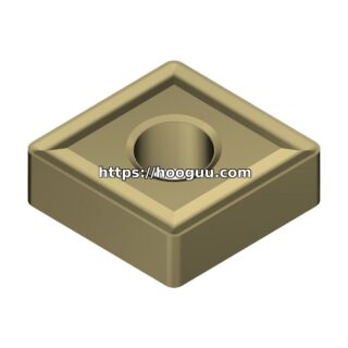
Insert Geometry for Turning PEEK
| Feature | Recommendation |
|---|---|
| Insert Type | CCMT, DCMT, or VCGT (positive geometry) |
| Rake Angle | +5° to +15° effective rake |
| Edge Preparation | Sharp — no honing, no T-land |
| Nose Radius | 0.2-0.4 mm for finishing, 0.4-0.8 mm for roughing |
| Grade | Uncoated fine-grain carbide: Korloy K10, Sandvik H13A, Iscar IC8 |
| Alternative | PCD for high-volume production (mirror-finish capability) |
Cutting Parameters: Turning PEEK
| Operation | Cutting Speed (m/min) | Feed (mm/rev) | Depth of Cut (mm) | Coolant |
|---|---|---|---|---|
| Rough Turning | 100-200 | 0.10-0.25 | 1.0-3.0 | Compressed air blast (preferred) |
| Semi-Finish | 150-250 | 0.08-0.18 | 0.5-1.5 | Air blast |
| Finishing | 200-400 | 0.05-0.12 | 0.1-0.5 | Air blast or mist coolant |
| Grooving | 80-150 | 0.05-0.10 | Groove width | Air blast |
| Parting Off | 60-120 | 0.04-0.08 | — | Air blast |
Cutting Parameters: Milling PEEK
| Operation | Cutting Speed (m/min) | Feed per Tooth (mm) | Radial Depth | Axial Depth | Coolant |
|---|---|---|---|---|---|
| Rough Milling | 150-300 | 0.05-0.12 | 50-70% of Ø | 1.0-2.0 × Ø | Air blast |
| Finish Milling | 250-500 | 0.03-0.08 | 10-30% of Ø | 0.3-1.0 × Ø | Air blast |
| Slotting | 100-200 | 0.03-0.06 | 100% (full slot) | 0.3-0.5 × Ø | Air blast |
| Contour Profiling | 200-400 | 0.03-0.08 | 5-20% of Ø | 0.5-1.5 × Ø | Air blast |
Cutting Parameters: Soft Plastics (PTFE, PE, PP)
| Operation | Cutting Speed (m/min) | Feed per Tooth / Feed (mm) | Coolant |
|---|---|---|---|
| Turning PTFE | 50-120 | 0.08-0.20 mm/rev | Air blast |
| Milling PTFE | 80-180 | 0.04-0.10 mm/tooth | Air blast |
| Turning UHMWPE | 80-150 | 0.10-0.25 mm/rev | Air blast |
| Drilling PEEK | 40-80 (surface speed) | 0.05-0.12 mm/rev | Peck cycle, air blast |
| Drilling PTFE | 30-60 (surface speed) | 0.04-0.10 mm/rev | Peck cycle, air blast |
Managing Thermal Issues
Heat management is the number one challenge in machining engineering plastics. Strategies:
1. Air Blast Over Flood Coolant. Most engineering plastics machine better with dry air blast than with flood coolant. Coolant can cause dimensional swelling in hygroscopic materials like PEEK and nylon, and it traps heat in the cutting zone by forming an insulating boundary layer. Use 4-6 bar compressed air directed at the cutting zone.
2. High Cutting Speeds with Light Depths. Counterintuitively, higher cutting speeds can reduce heat input per unit volume because the chip carries heat away faster. Light depths of cut (0.1-0.5 mm) keep cutting forces low and minimize heat generation.
3. Intermittent Cutting. For deep pockets or long turning passes, pause periodically to allow heat dissipation. The low thermal conductivity means the heat stays localized — a 10-second pause can drop the cutting zone temperature by 30-50°C.
4. Sharp Tools Only. A dull tool generates 2-3× more frictional heat than a sharp one. Replace or rotate end mills at the first sign of edge degradation — typically 0.05-0.10 mm flank wear for plastics.
Achieving Surface Finish
PEEK and engineering plastics can achieve excellent surface finishes when machined correctly:
| Material | Roughing Ra | Finishing Ra (Carbide) | Finishing Ra (PCD) |
|---|---|---|---|
| PEEK (unfilled) | 1.6-3.2 μm | 0.4-0.8 μm | 0.2-0.4 μm |
| PEEK (30% CF filled) | 2.0-4.0 μm | 0.8-1.6 μm | 0.4-0.8 μm |
| PTFE | 3.2-6.3 μm | 0.8-1.6 μm | 0.4-0.8 μm |
| PEI (Ultem) | 1.6-3.2 μm | 0.4-0.8 μm | 0.2-0.4 μm |
| PPS (Ryton) | 1.6-2.5 μm | 0.4-1.0 μm | 0.2-0.6 μm |
Note on carbon-fiber-reinforced PEEK: CF-filled PEEK is significantly more abrasive than unfilled grades. Tool life drops by 50-70% compared to unfilled PEEK. Use PCD inserts for production runs, and reduce cutting speeds by 20-30% to manage abrasive wear from the carbon fibers.
Dealing with Springback and Dimensional Accuracy
Engineering plastics exhibit elastic recovery after cutting — the machined surface springs back slightly after the tool passes. This can cause:
- Bored holes to close up by 0.02-0.10 mm
- Turned diameters to grow by 0.01-0.05 mm
- Milled walls to shift by 0.02-0.08 mm
Compensation strategies:
- Program a spring finish pass with 0.05-0.10 mm depth of cut at the same coordinates
- Allow 0.03-0.08 mm oversize on critical dimensions and finish with a dedicated spring pass
- Use sharp tools with high positive rake to minimize elastic deformation during cutting
- For holes, ream 0.02-0.05 mm oversize to account for springback
Workholding Considerations
Engineering plastics are easily deformed by clamping forces. Excessive clamping can permanently distort the workpiece, and after unclamping, the part springs back out of tolerance. Use:
- Low clamping pressure — soft jaws with wide contact area
- Vacuum chucks for flat parts (particularly effective for PEEK and PEI)
- Adhesive-backed fixturing for thin-walled or delicate features
- Step-by-step machining: rough all features, release the part, re-clamp lightly, then finish
Summary
PEEK and engineering plastics demand sharp, polished, high-clearance tools with positive rake geometry. Uncoated fine-grain carbide (Korloy K10, Iscar IC8) is the standard; PCD is the premium option for production volumes. Always use compressed air blast instead of flood coolant. Maintain high cutting speeds with light depths of cut, and program spring passes on critical dimensions to account for elastic recovery. With proper technique, PEEK can be machined to tolerances of ±0.01 mm and surface finishes below Ra 0.4 μm.
hooguu.com offers a selection of polished-flute carbide end mills, sharp-edged inserts, and PCD tools specifically suited for machining PEEK, PTFE, PEI, and other engineering plastics. Contact our technical team for tooling recommendations for your medical device, semiconductor, or aerospace plastic components.
Shop Related Products at HOOGUU