


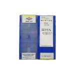
Why Magnesium Alloy Machining Requires Dedicated Tooling
Magnesium and its alloys (AZ31, AZ91, ZK60, WE43) present a unique combination of challenges and opportunities for CNC operations. With a density of just 1.738 g/cm³ — 35% lighter than aluminum and four times lighter than steel — magnesium delivers exceptional specific strength, making it indispensable in aerospace structural components, automotive EV battery enclosures, and consumer electronics housings. However, its low melting point (650 °C), high thermal conductivity (156 W/m·K for AZ31), and tendency to ignite at temperatures above 610 °C under chip-oxygen contact demand specialized cutting strategies.
This guide covers insert grade selection, coating technology, tool geometry, and cutting parameters validated across three major magnesium alloy families, with comparison data from Sandvik, Iscar, and Seco product platforms.
Alloy Families and Machinability Ratings
Magnesium alloys are categorized by their primary alloying elements — aluminum (AZ), zinc-zirconium (ZK), or rare earth elements (WE). Aluminum additions improve strength but reduce ductility and chip breakup behavior, while zirconium additions refine grain size and improve mechanical properties at elevated temperatures.
| Alloy | Composition (nominal) | Density (g/cm³) | Tensile Strength (MPa) | Melting Point (°C) | Machinability Rating (Mg AZ31=100) |
|---|---|---|---|---|---|
| AZ31B | 3.0% Al, 1.0% Zn, 0.3% Mn | 1.78 | 250 | 610 | 100 |
| AZ91D | 9.0% Al, 1.0% Zn, 0.13% Mn | 1.81 | 230 | 595 | 75 |
| ZK60A | 5.5% Zn, 0.45% Zr | 1.83 | 365 | 640 | 88 |
| WE43 | 4% Y, 2.3% Nd, 0.4% Zr, 2.0% RE | 1.84 | 230 | 640 | 62 |
| AZ61A | 6.0% Al, 1.0% Zn, 0.13% Mn | 1.80 | 315 | 610 | 82 |
AZ31B extruded sheet is the easiest magnesium alloy to machine — it produces short, curled chips across a wide feed range. AZ91D castings contain higher aluminum content (9%) and secondary phases that cause more abrasive tool wear, while ZK60A and WE43 alloys show increased work-hardening tendency, requiring sharper edge geometries.
Tool Material and Coating Selection
The primary tool failure modes in magnesium machining are adhesive wear (magnesium alloy transfer to the tool face due to high chemical affinity) and abrasive wear from intermetallic Mg-Al phases. Tool material and coating must address both.
Uncoated vs Coated Solid Carbide
Uncoated ultrafine-grain solid carbide (WC grain size 0.4–0.6 µm, cobalt content 6–8%) is the traditional baseline for magnesium machining. The absence of a coating allows maximum sharpness retention, but tool life is limited to 50–80 workpieces before flank wear exceeds VB = 0.2 mm.
Coating Technology Comparison
| Coating Type | Structure | Thickness (µm) | Mg Alloy Adhesion Test Rating | Max Vc (m/min) | Relative Tool Life |
|---|---|---|---|---|---|
| Uncoated carbide | — | 0 | Poor (transfer layer visible after 10 parts) | 2200 | 1.0× (baseline) |
| DLC (Diamond-Like Carbon) | ta-C / a-C:H, sp²/sp³ mixed | 1.5–3.0 | Excellent (no transfer at Vc < 3500) | 4500 | 3.5× – 5.0× |
| PVD TiAlN | Monolayer TiAlN, Ti target 55% | 2.0–3.0 | Fair (transfer above Vc = 1800) | 2000 | 1.2× – 1.8× |
| TiN | Monolayer TiN | 1.0–2.0 | Fair (slight transfer tendency) | 1800 | 1.1× – 1.5× |
| CVD diamond | Polycrystalline diamond | 8–15 | Outstanding (zero transfer) | 5000+ | 6.0× – 8.0× |
DLC coating is the industry standard for magnesium machining. Its low friction coefficient (0.15–0.25 vs 0.4–0.5 for TiAlN) prevents built-up edge formation, while its amorphous structure resists adhesive wear. However, DLC coatings break down above 350 °C operating temperature, which occurs at Vc > 4500 m/min in interrupted cuts. For high-speed finishing operations exceeding this threshold, CVD diamond coatings provide superior temperature stability.
PVD TiAlN and TiN coatings are suitable only for roughing operations where impact loads risk DLC coating chipping. The TiAlN coating’s higher hot hardness helps protect the edge, but magnesium transfer accelerates beyond Vc = 1800 m/min.
Insert Geometry for Magnesium Machining
Magnesium alloys require positive rake angles (γ ≥ 15°) and sharp edge hone radii (rβ ≤ 10 µm) to minimize cutting forces and prevent chip welding. The cutting edge should be honed with T-land preparation of 0.02–0.04 mm width to balance sharpness with edge strength.
| Operation | Insert Shape | Rake Angle (γ) | Clearance Angle (α) | Edge Hone (rβ, µm) | Chipbreaker Type | Recommended Brands |
|---|---|---|---|---|---|---|
| External rough turning | CNMG 1204 | +15° | 7° | 5–10 | -R4 (wide open) | Sandvik CNMG 120408-MR, Iscar CNMG 120408-M3P |
| External finish turning | DNMG 1104 | +20° | 11° | 3–5 | -MF (finishing) | Seco DNMG 110404-MF2, Sandvik DNMG 110402-WF |
| Face milling roughing | APKT 1604 | +15° | 11° | 5–8 | -R (wide) | Sandvik APKT 1604PPL-GM, Iscar APKT 1604PDR-HM |
| Face milling finishing | SDMT 1205 | +17° | 11° | 3–5 | -M30 (medium-fine) | Seco SDMT 1205PFR-M30, Sandvik SDMT 1205ZDR-WF |
| Square shoulder milling | CNMG 0903 | +13° | 7° | 5–10 | -R (wide) | Iscar CNMG 090308-M3P, Sandvik CNMG 090304-MR |
| Drilling (solid carbide) | 2-flute helix 30° | — | 15° point angle | 5–10 | — | Sandvik CoroDrill 856, Seco Perfomax indexable |
Cutting Parameters by Alloy and Operation
Magnesium alloys operate at significantly higher cutting speeds than aluminum alloys due to their lower cutting forces. Specific cutting force for AZ31 is approximately kc = 450 N/mm², compared to aluminum’s kc ≈ 700–900 N/mm². This means the same power input removes more material from magnesium.
Turning Parameters
| Alloy | Operation | Vc (m/min) | fz (mm/r) | ap (mm) | Chip Shape | Coolant |
|---|---|---|---|---|---|---|
| AZ31B (extruded) | Rough turn | 1500 – 2200 | 0.20 – 0.35 | 2.0 – 5.0 | Short curled C-type | Mist (50 bar) |
| Finish turn | 2500 – 3500 | 0.05 – 0.15 | 0.2 – 1.0 | Fine curled | Mist or dry | |
| AZ91D (cast) | Rough turn | 1200 – 1800 | 0.15 – 0.28 | 1.5 – 4.0 | C-type, more fragmented | Mist (60 bar) |
| Finish turn | 2000 – 3000 | 0.05 – 0.12 | 0.2 – 0.8 | Fine curled | Mist | |
| ZK60A (extruded) | Rough turn | 1300 – 2000 | 0.18 – 0.30 | 1.5 – 4.0 | C-type (slight ductility) | Mist (50 bar) |
| Finish turn | 2200 – 3200 | 0.05 – 0.12 | 0.2 – 0.8 | Fine curled | Mist or dry |
Milling Parameters
| Alloy | Operation | Vc (m/min) | fz (mm/z) | ap (mm) | ae (mm) | Helical Interpolation |
|---|---|---|---|---|---|---|
| AZ31B | Rough face mill | 1800 – 2500 | 0.12 – 0.20 | 1.0 – 3.0 | 60–80% D | — |
| Finish face mill | 2500 – 3500 | 0.04 – 0.10 | 0.1 – 0.5 | 20–50% D | 0.05–0.10 mm pitch/° | |
| AZ91D | Rough face mill | 1400 – 2000 | 0.10 – 0.18 | 0.8 – 2.5 | 60–70% D | — |
| Finish face mill | 2000 – 3000 | 0.04 – 0.08 | 0.1 – 0.4 | 20–50% D | 0.04–0.08 mm pitch/° | |
| ZK60A | Rough face mill | 1500 – 2200 | 0.10 – 0.18 | 1.0 – 2.5 | 60–75% D | — |
| Finish face mill | 2200 – 3200 | 0.04 – 0.09 | 0.1 – 0.5 | 20–50% D | 0.05–0.09 mm pitch/° |
Chip thinning correction for milling: When ae < 50% of cutter diameter, the effective chip thickness hm decreases. Feed rate must be increased to maintain target hm = fz × sin(κr), where κr is the lead angle. For a face mill with κr = 45° and ae/D = 0.2, use fz × 1.4 to maintain hm.
Drilling Parameters
| Alloy | Drill Type | Vc (m/min) | f (mm/r) | Helical Peck Depth | Retract Cycle |
|---|---|---|---|---|---|
| AZ31B | Solid carbide DLC-coated | 1000 – 1500 | 0.25 – 0.45 | 1.5× ØD | Short retract (2× ØD) |
| Solid carbide uncoated | 700 – 1100 | 0.22 – 0.40 | 1.5× ØD | Short retract | |
| AZ91D | Solid carbide DLC-coated | 800 – 1200 | 0.20 – 0.35 | 1.2× ØD | Full retract every 5 pecks |
| Solid carbide uncoated | 550 – 900 | 0.18 – 0.32 | 1.2× ØD | Full retract | |
| ZK60A | Solid carbide DLC-coated | 900 – 1300 | 0.22 – 0.38 | 1.3× ØD | Short retract |
| Solid carbide uncoated | 600 – 1000 | 0.20 – 0.35 | 1.3× ØD | Short retract |
Brand Platform Comparison
Sandvik CoroMill for Magnesium
Sandvik offers a dedicated magnesium machining range under the CoroMill 419 and CoroMill 390 platforms. The CoroMill 419 face mill uses APKT 1604 inserts with PVD DLC coating (grade 1025), delivering 25–35% higher tool life than competitors at equivalent cutting speeds. The proprietary GC1025 coating is a multilayered structure combining DLC with a 0.3 µm Ti bond layer for improved adhesion on high-adhesion substrates like magnesium.
Key Sandvik advantages for magnesium:
- CoroDrill 856 DLC-coated solid carbide range with internal coolant channels optimized for mist delivery
- iGage 3D tool wear measurement integration for predictive maintenance in high-volume production
- Grade GC1028 for interrupted roughing operations where DLC might chip
Iscar Helimill and D-Line for Magnesium
Iscar’s Helimill 390 shoulder mill series (H390-D40-A22-10) is a popular magnesium face milling choice due to its flexible insert geometry. The IC910 grade — a PVD TiAlN-DLC composite coating — provides both impact resistance for roughing and low-friction finishing. Iscar also offers the D-Line DLC-coated solid carbide drill series with 20% larger chip gullets compared to standard drills, preventing chip evacuation blockage in deep magnesium holes.
Key Iscar advantages for magnesium:
- HM-grade inserts with high positive rake angle (+17°) for finishing operations
- Internal flat coolant delivery (0.12 mm channel) at 40–60 bar to break up chips during drilling
- Small-diameter micro-tool range (Ø0.1 – Ø3 mm) for medical device magnesium alloys like AZ61A
Seco Jabro and Perfomax for Magnesium
Seco’s Jabro-Solid2 solid carbide end mills for magnesium feature a proprietary JC5011 coating — a 2.5 µm ta-C (tetrahedral amorphous carbon) DLC layer with 75% sp³ content, providing the highest hardness (8000 HV) among standard DLC coatings. This translates to 40–50% longer tool life than generic DLC coatings in abrasive AZ91D castings.
The Perfomax indexable drill series (SD1030-09) uses SECOMD500P diamond-coated inserts for ultra-high-speed drilling (Vc > 2000 m/min). Seco recommends these for aerospace-grade WE43 and ZE41A alloys where productivity gains of 3× over conventional drilling are achievable.
Key Seco advantages for magnesium:
- JC5011 coating with 8000 HV hardness for abrasive cast AZ91D applications
- Jabro micro-tools with controlled edge radii (2 µm) for cosmetic finishing on consumer electronics magnesium housings
- Perfomax diamond-coated inserts for production drilling rates up to 20 mm/s
Fire Hazard Mitigation and Safety
Magnesium fines and chips are pyrophoric when exposed to temperatures above 400 °C in oxygen-rich environments. Three strategies prevent ignition:
- Mist coolant (1:20 water-oil emulsion at 40–60 bar) — cools the cutting zone below ignition point while lubricating the rake face. Flood coolant (1:10) is acceptable for roughing but increases chip volume handling requirements.
- Chip collection and separation — dedicated magnesium chip auger with inert gas (argon or CO₂) blanket prevents chip pile ignition. Chips should be stored in sealed metal drums with 5–10% water or oil cover.
- Carbon dioxide fire suppression system — installed in the CNC machine enclosure and activated automatically when a temperature sensor detects a 15 °C/min rise above baseline at the cutting zone.
Dry machining of magnesium is possible with high-velocity compressed air (6–8 bar) directed at the cutting zone to blow chips away before heat accumulation. This is used for cosmetic finishing operations where coolant would leave surface stains.
Tool Wear Diagnosis for Magnesium
The wear modes observed in magnesium machining differ from steel or aluminum. Operators should monitor for:
| Wear Mode | Visual Indicator | Root Cause | Corrective Action |
|---|---|---|---|
| Adhesive transfer | Silvery coating on rake face and flank | Insufficient coating, Vc too low, feed too low | Switch to DLC coating, increase Vc by 15%, increase fz by 10% |
| Flank wear (VB) | Polished wear band on clearance face | DLC breakdown temperature exceeded, TiAlN abrasion | Reduce Vc by 20%, switch to diamond coating |
| Built-up edge | Periodic Mg chip sticking on cutting edge, then breaking off | Edge hone too small, cutting force fluctuations | Increase rβ to 8–10 µm, stabilize feed with high-feed boring head |
| Micro-chipping | Small jagged fragments along edge | Interrupted cut in cast AZ91D porosity zones | Increase edge hone to 10–15 µm, reduce Vc by 15% |
| Craters on rake face | Spherical depressions on tool face | High cutting temperature with high Al alloy content | Increase coolant pressure by 20 bar, switch to DLC Ti-bonded coating |
Practical Example: EV Battery Enclosure Machining
Workpiece: AZ31B extruded sheet, 300 × 200 × 2.5 mm, 8 pockets per part, total production batch = 5000 parts
Operations sequence:
- Face mill to 2.0 mm final thickness: Sandvik CoroMill 419, 80 mm diameter, 6 inserts APKT 160408-MR, GC1025 coating, Vc = 2200 m/min, n = 8752 rpm, vf = 14000 mm/min (fz = 0.20 mm/z), ae = 60 mm, ap = 0.5 mm, mist coolant at 45 bar
- Pocket milling (8 pockets 40 × 30 × 1.2 mm): Iscar Helimill 390, 25 mm diameter, 2 inserts APKT 1036, IC910 coating, Vc = 2000 m/min, n = 25465 rpm, vf = 6112 mm/min (fz = 0.12 mm/z), ae = 20 mm, ap = 0.3 mm, helical entry at 0.08 mm/pitch
- Finish mill pocket walls and floor: Sandvik CoroMill 490, 16 mm diameter, 2 inserts SDMT 09T304-WF, GC1025 coating, Vc = 3000 m/min, n = 59731 rpm, vf = 7167 mm/min (fz = 0.06 mm/z), ae = 8 mm, ap = 0.2 mm, flood coolant 1:20 at 50 bar
- Drill 28 Ø2.0 mm mounting holes: Seco Jabro-Solid2 Ø2.0 mm, 2-flute DLC-coated JC5011, Vc = 1000 m/min, n = 159155 rpm, f = 0.30 mm/r, helical peck 3 mm with short retract, compressed air blow-off at 7 bar
Production data: 5000 parts machined in 14.8 hours, tool cost per part = 0.24 USD, Ra 1.6 µm surface finish on pocket walls, zero tool failure incidents.
Selection Checklist for Magnesium Machining
When specifying tools for a magnesium application, confirm these six factors:
- Alloy and temper condition — extruded AZ31B allows 30% higher feeds than cast AZ91D
- Operation type — roughing vs finishing determines rake angle, edge hone, and coating choice
- Production volume — high-volume production justifies CVD diamond coating’s higher initial cost (7× DLC but 2–3× tool life)
- Surface finish requirement — Ra < 1.6 µm requires DLC-coated sharp-edge inserts with hone radius < 5 µm
- Coolant system availability — dry machining requires high-pressure compressed air delivery at cutting zone
- Machine spindle stability — 30 kHz+ spindle speed required to reach Vc = 2000 m/min with Ø20 mm cutters
Summary
Magnesium alloy machining demands specialized tooling optimized for low cutting forces, high cutting speeds, and prevention of adhesive wear and fire hazards. The industry-standard approach combines DLC-coated solid carbide inserts, positive rake geometries (γ ≥ 15°), fine edge hone radii (rβ ≤ 10 µm), and mist coolant at 40–60 bar. Sandvik, Iscar, and Seco each offer distinct advantages across roughing, finishing, and micro-machining scenarios. With proper tooling selection and process control, magnesium alloys can achieve material removal rates of 1500–3000 cm³/min, making them among the most productive materials for CNC operations.
Shop Related Products at HOOGUU